
WSPR
NEW:- Dec 2023, added BOM, Sch and Sketch.
home
| ESP8266 WSPR Tx ONLY |
I take no credit for this project other than the changes I made for it to have an OLED display also. I originally found this idea from a sketch by IW5EJM which is here. But it was improved by NT7S. There is also a similar project by Tom Igoe & Ivan Grokhotkov. And a VK (don't know callsign) UPDATE: Try https://antrak.org.tr/blog/basit-ve-ucuz-esp-wspr-vericisi/ You may need to use Translate to see in English or other language. Or check this Blog (Apr 2023) http://blog.marxy.org/2021/09/simple-wspr-beacon-using-si5351-and.html Note this project, while similar in some ways to the QRP_Labs "U3S" kit, all parameters are hard coded and cannot be changed while in operation, as the U3S can be.
Initially, the project will be built onto some Proto PCB material to contain the above modules. For a display I used a 0.96" OLED display and adapted the sketch in the link above to use it. While small, it's not anticipated that one needs to constantly monitor the WSPR Tx, but is a nice guide where you can see current status at a glance. For those inclined, it would be fairlt simple to change to say a TFT colour display, to make text larger and 'pretty' and add some more details of the WSPR "progress" or state. There are various OLED displays available, the one I used is I2C interface only, (It's I2C adddress is 0x4c) but there are others which can be switched to I2C via a simple change shown on the back of module. I used the I2C only module which has 4 pins, others may have more pins but ensure that they can be used in I2C mode. |
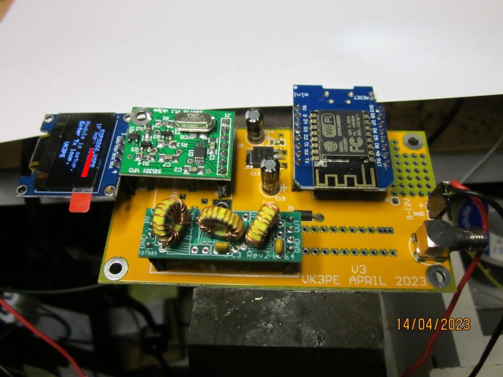
PROGRESS: UPDATED April 14th 2023 I now have an actual PCB for this project as I was getting some others made through the usual Chinese sites and added this one in. While yet to be tested on-air, it appears to be working fine. Note my addition of an OLED dsiplay over the original design. While the picture shows the OLED connected to my PCB at left, it would normally be mounted off board using a 4 way cable, for a better integration into a suitable case. The SMA connector to the right side is the RF output, to the antenna. I use an EFHW antenna. Power supply is 12v, regulated down to 5v on the PCB.
--------------------------------- At this point, it's late Jan 2023 and the project has been bench tested only. One of the 'downsides' of the project is the output is just 10mW. I plan to boost this to about 150-200mW with an extra 'PA' stage later. |
|
|
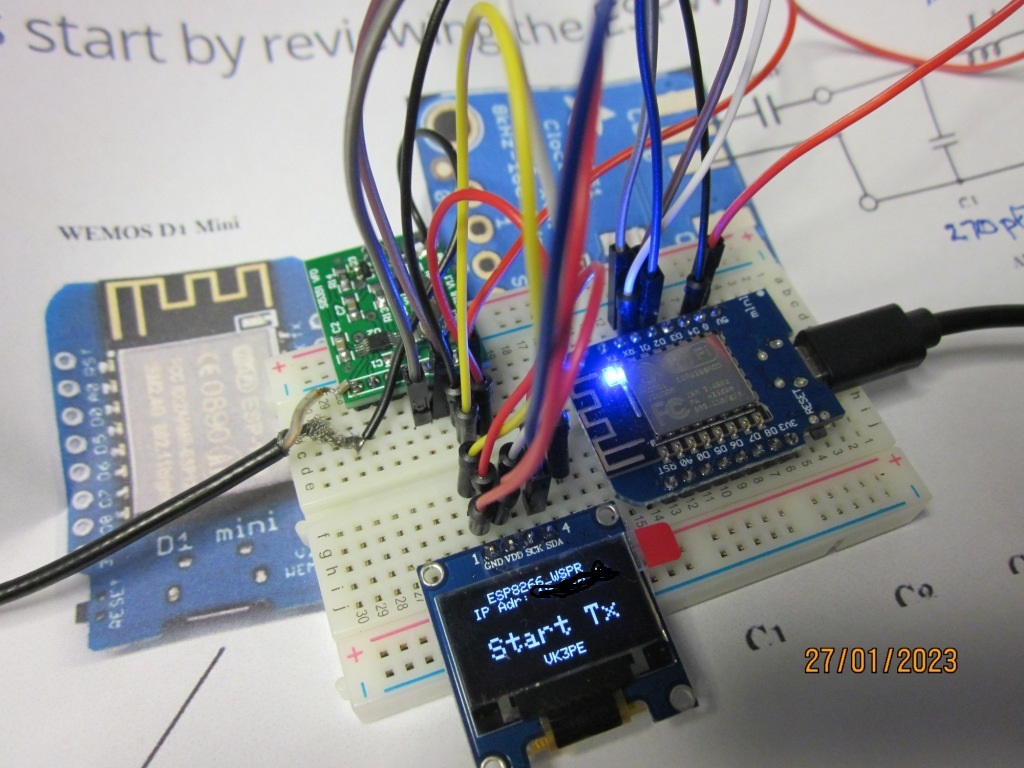
The proto WSPR project: Here is the bench test of the ESP8266 board plus Si5351 board. Rather than use the Adafruit or similar Si5351 module, as you can see, I had previously made my own smaller versions some time ago.
All that is required to use the OLED display is to add the appropriate code into the sketch and connect it to the same I2C lines that the Si5351 board uses. Both have different I2C addresses so there is no conflict. The Si5351 address is 0x3C. The beauty of using the ESP8266 module, is that it has in-built WiFi which in this case, is used to get accurate time on the server. The modified sketch will here soon. The original can be found on the link above. I modified the original sketch to operate on the 30M band rather than the 20M band of the original. Schematic is identical to the link, however once I add the 'PA' stage and a voltage regulator for it to run from an external supply (rather than USB) it will of course change. I will add it later. Bill of material, see the link above and my own BOM once I complete the project. NOTE: I have obliterated my IP address on the display.
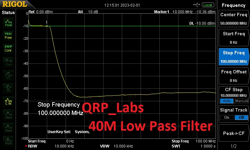
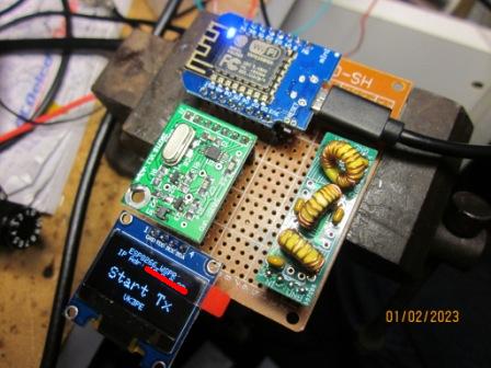
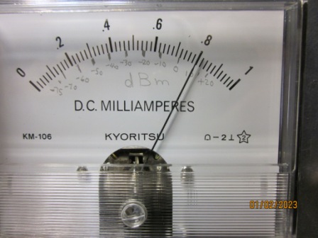
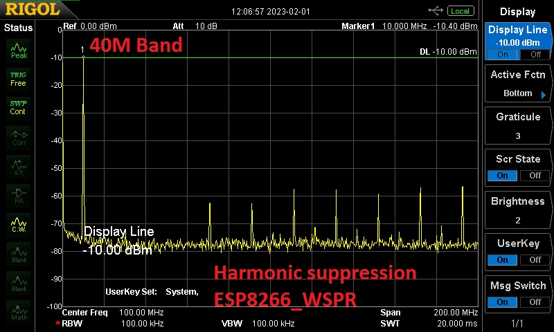
And now, the proto PCB material. Not pretty, but a quick and cheaper way to build it. Normally the OLED display would be fitted on a panel etc. The (AD8307 based) meter shows the power output at +10dBm, or 10mWatts. (pencil scale) Also confirmed with the SA. The QRPLabs Low Pass filter is the small green PCB with toroids. The blue PCB is the ESP8266 while the other green PCB is my own version of an Adafruit Si5351 module.
|
This project operates on Amateur bands only and a licence is required, according to the authority in your jurisdiction. No guarantees are given or implied as to the suitability of this material for any purpose whatsoever. Information herein is presented for amusement or entertainment only. Any inadvertant use of Trademarks is accidental and not an endorsement or otherwise of a product.
Page created on 27th Jan 2023 and last updated on December 16, 2023 13:22 by VK3PE (See QRZ.COM) |