 I have placed a short wire in two place on 80M band. All bands are affected,
the "B" and "D" capacitors. Click picture for larger size.
(Not all caps have been fitted yet) I left the wire a little long here so it
is easier to see.
I have placed a short wire in two place on 80M band. All bands are affected,
the "B" and "D" capacitors. Click picture for larger size.
(Not all caps have been fitted yet) I left the wire a little long here so it
is easier to see.Errors on COMBO PICASTAR PCB panel, Version "C" (prototype board)
last updated:- September 26, 2011
This Beta batch of PCB's was made to find any possible errors in the PCB. Unfortunately, there are some, but easily overcome. Later versions, if a new batch is made, will be corrected.
MAIN BOARD
1) The holes for the RTC battery have been drilled oversize. The battery can still be fitted though.
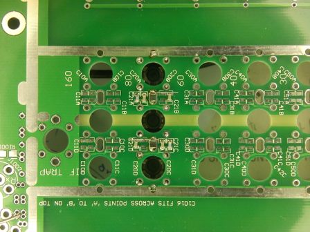
2) There was a 'hiccup' in the bottom ground area in the BPF area. The tuning caps have no ground. This is easily repaired by running a very short piece of tinned copper wire from the Caps to the adjacent ground lugs for the Toko coil formers.
 I have placed a short wire in two place on 80M band. All bands are affected,
the "B" and "D" capacitors. Click picture for larger size.
(Not all caps have been fitted yet) I left the wire a little long here so it
is easier to see.
3) Minor issue. The text adjacent to pin 2 of J9 says '5v'. It should say 'gnd'. Pin 1 is '5v'
4) There is a ground missing on IC8 under the PCB. Fit a short wire as shown.
5) This was intentional, but you need to fit 2 wire links as shown in the Trxavrb area. I have made them a little longer here so it is clearer. NOTE: do not fit an IDC cable here, it is not required.
6) The overlay for diode D504 in the MR area has the cathode marking at the wrong end. Please insert the diode the other way round ! (If you don't, sensitivity in the best IP3 mode will be severly degraded.)
140W PA BOARD:-
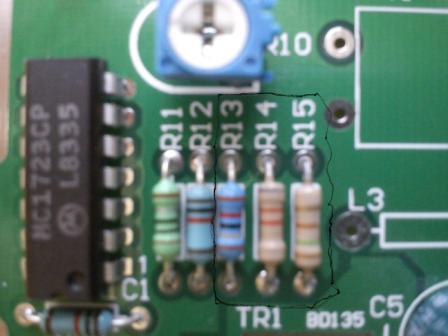
1) PLEASE NOTE ! the values of R13, R14 & R15 are shown INCORRECTLY on the PCB overlay. Please use the link here to get the correct values.
