KEN's Porto Combo PICASTAR build.
Ken, G3LVP, has also built a PICASTAR using my single board Combo panels. This is his latest build which is complete and has been tested on air already!
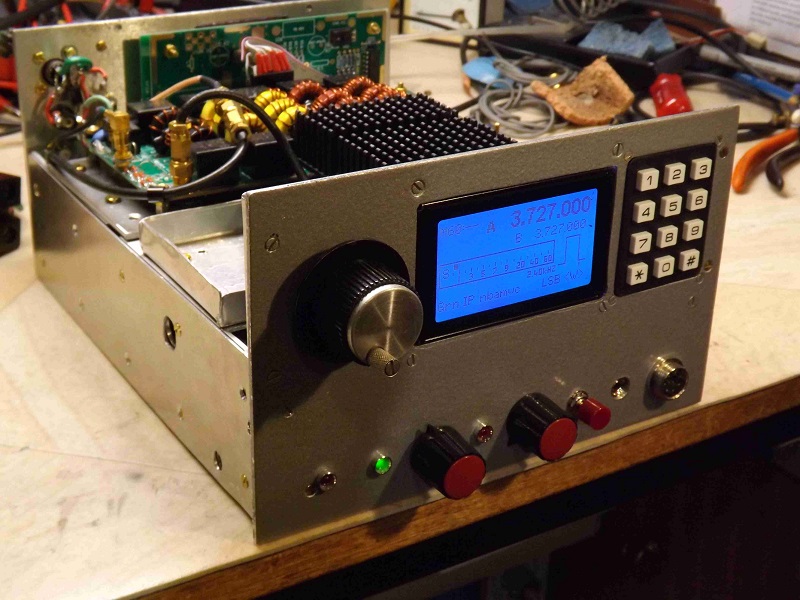
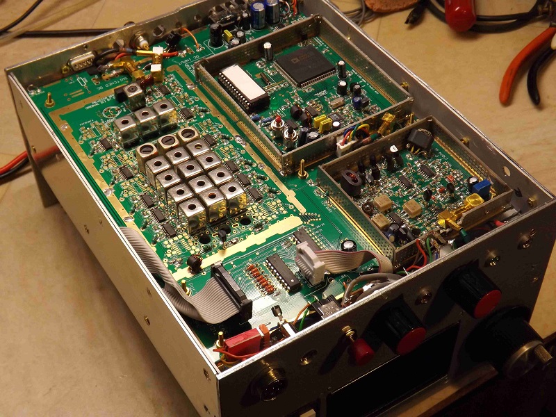
As you can see in the pictures below, Ken's Porta Combo (P2 version) is all assembled and being 'bench tested'. Ken has fitted some SMA connectors also in some areas.
Page last updated on:- March 24, 2014
>> Glenn
>> I thought that you might be interested to
see a couple of pics of my
>> 'Porto' in its almost finished state (all that's missing id the 100W
PA)
>>
>> The PCB containing the TrxAVR, LO etc. sits under the 20W driver
>> stage and LPF, these two units are secured with a few screws &
come
>> off easily, getting the PCB's out is a different matter and requires
>> taking the front panel off and that involves removing a few more
>> screws. It would have made it much easier if I'd drilled all of the
>> PCB fixing holes accurately and made the whole thing a couple of
>> inches bigger all round!
>>
>> Again thanks for your help & encouragement.
>>
>> 73...
>>
>> Ken
November, 27th, 2013
Hi Glenn,
It's all thanks to you, I doubt that I would ever have built even one 'Star if it hadn't been for your work on the PCB's.
A few observations, I found that getting the Porto going was a bit more difficult than the Combo which goes to show what a good design the Combo
was.
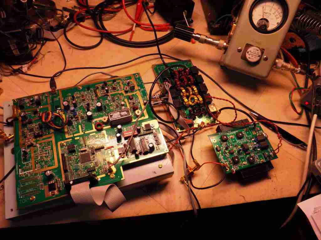
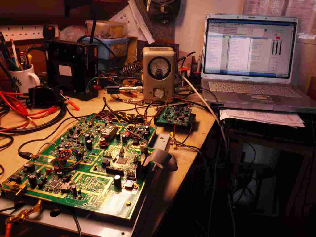
Working with the two boards connected together on my rather small (untidy?) bench until they were both mounted on the 'tray' was a bit
tricky, it would have been easy to have shorted something out. See the pic's, the power meter is indicating 15W on 80 m. The 20W PA should be
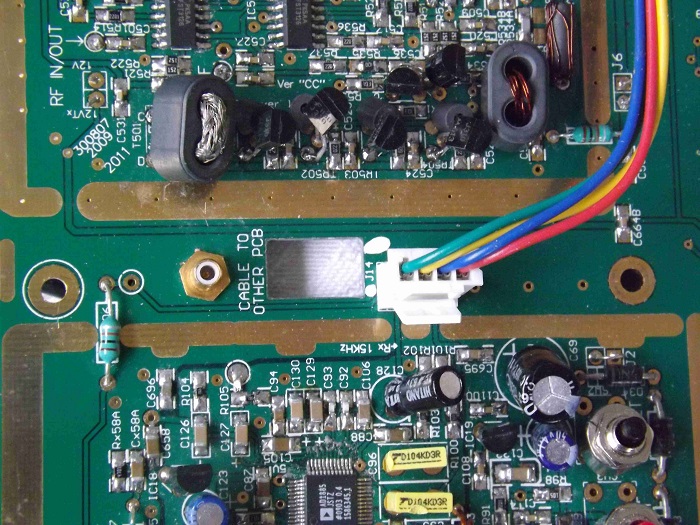
giving a bit more so there's some work to be done there. I connected the two15kHz signal connections via a pair of flying leads with mono
jack/plugs, I'm going to change that & just use a single stereo plug/socket.Rather than using T/R status which I guess is the intended switching line for the Antenna c/o relay on the TZR LPF I've grounded one side of
that relay so that I can use the 12v 'PA' bias line which is on JP401, this saves running a flying lead from Status but means that the Ant. relay timing follows the
PA bias rather than having its own timing. I did this on the Combo & so far its not caused a problem. One day I may think about this again but I don't
like using relays for antenna c/o & prefer to use solid state switching as the K3 does but I think it needs -150 v bias.I thought about using a SMB connector for the I/P-O/P to the 10.7 IF by drilling a hole beside RFC 603 but not being sure what might be drilling
into so I've put that on hold for the moment. I'd prefer to use another SMB at the MR end as well as I'm not keen on flying leads.I've managed to fit an SMA as the I/P to the 'TZR LPF and an SMB as the RX O/P but haven't yet drilled a hole for an SMA for the antenna connection
(SMA's are more than adequate at 100w).I'm waiting to get into the garage to do some metal work but today it's only 4 deg and went down to -2.5 last night. I'm thinking about using a
TFT display but will have to study that some more. I'm not sure whether the TrxAVR drives a non-touch screen TFT directly or needs an interface board, (so
far I've not found the answer on the TFT-a central) or whether I'm actually going to have room for a TFT as the case that I have allows for
a panel size of 8.25" x 5". I might end up using another 128 x 64 mono display but the colour TFT looks much better.73...
Ken
G3LVP
Dec 2013: Ken has fitted SMB co-ax connectors in part of the project. The PCB's are not designed originally to take them (apart from the BPF and LO areas) but Ken has managed to massage the PCB's to fit them.
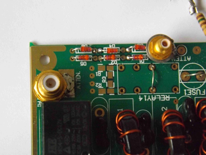 Low pass filter
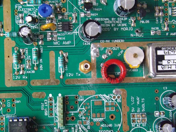 The IF input
page created by vk3pe, 27th Nov,2013