USING A HI-PULSE COUNT ROTARY ENCODER IN PLACE OF LOW COUNT ENCODERS.
This web page was last updated on
January 18, 2022
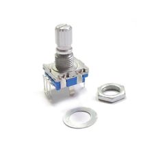
Many projects use the cheap eBay and other suppliers, grey scale mechanical rotary encoders which usually have about 16 pulses per turn. Typical encoder shown below.
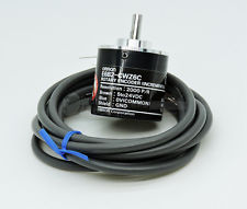
The next tier up from these types of encoders are the high pulse count encoders, often using optical devices internally. Output pulses per full rotation, can be very high. The particular one I have is a 360pulse type. It’s a very high quality optical device and requires a 5v supply to operate, compared to the cheap types, which are totally passive, relying on switch contacts for their operation.
I wanted to use this 360 pulse encoder in a project as a direct replacement for the 16 pulse count type, without having to modify the code in the actual device. In my case, a home brew HF rig.
 There is a lot of talk about doing this, in a web search, but nobody who has done it, or at least, published any details. My idea was to use an Arduino to do the job and after a number of attempts, got nowhere useful. More searching found http://ok1fig.nagano.cz/EncoderDivider/EncoderDivider.htm who uses a series of Logic Chips to do it. If you look on his web page you will see it’s relatively complex, with 7 chips on his PCB. His implementation takes up a lot of space. I emailed him asking for further details, but got no reply, so continued with the Arduino idea, using an ATtiny85 Micro, a small under $2, 8 pin chip. (I used the DIP package as it’s easier to physically program.) It’s much more difficult than it seems, and made even more difficult with my limited C++ experience! The smaller code space ATtiny devices should also work but the ‘85’ is probably more commonly available. There is a lot of talk about doing this, in a web search, but nobody who has done it, or at least, published any details. My idea was to use an Arduino to do the job and after a number of attempts, got nowhere useful. More searching found http://ok1fig.nagano.cz/EncoderDivider/EncoderDivider.htm who uses a series of Logic Chips to do it. If you look on his web page you will see it’s relatively complex, with 7 chips on his PCB. His implementation takes up a lot of space. I emailed him asking for further details, but got no reply, so continued with the Arduino idea, using an ATtiny85 Micro, a small under $2, 8 pin chip. (I used the DIP package as it’s easier to physically program.) It’s much more difficult than it seems, and made even more difficult with my limited C++ experience! The smaller code space ATtiny devices should also work but the ‘85’ is probably more commonly available.
I am in regular contact with Jim, G3ZQC, who very kindly took a look at my sketch and made some changes. Well, lots of changes. After a few iterations, a very workable solution was made by Jim and it proved to work reliably in my uBITX rig. It currently divides by ‘12’. While it should work with other ratios, it’s only been tested at 12 so far. It gives about 2 KHz of frequency change for example, for a single knob rotation, when used in my uBITX “Raduino” test board.
 Programming the ATtiny85 in the Arduino IDE needs some understanding also. You can Google how to do it, especially setting up the environment so that ATtiny device sketches can be compiled. Next problem is actually programming the devices. I found this web page to be most helpful and made up a little jig to hold the DIP8 package ATtiny device according to http://highlowtech.org/?p=1706 Programming the ATtiny85 in the Arduino IDE needs some understanding also. You can Google how to do it, especially setting up the environment so that ATtiny device sketches can be compiled. Next problem is actually programming the devices. I found this web page to be most helpful and made up a little jig to hold the DIP8 package ATtiny device according to http://highlowtech.org/?p=1706
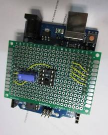
Figure 3 shows my “programmer adapter’ to program the DIP package ATtin85, fitted to an Arduino “UNO” board. It was wired up as per the link above. Also see https://www.instructables.com/id/How-to-Program-an-Attiny85-From-an-Arduino-Uno/
Once programmed, the ATtiny85 is transferred to your own project PCB.
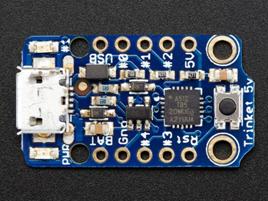
You could also use one of the pre-made PCB’s like the Arduino “Trinket” or similar boards found on eBay. This is for information only, as I don’t have one of these boards to test yet.
The Trinket uses an ATtiny85 and is shown to the left, note this is the 5v version. There is also a 3.3v version.
Check the Adafruit web page for details for programming this part.

This is a typical eBay ATtin85 PCB which also has the USB port. Not sure if it's for programming.
As far as I am aware, you may be able to program the eBay version in the same manner as the Adafruit one. Refer to the Adafruit web page for programming details. HOWEVER, until I get one, I can't confirm that it has a bootloader.
For my own actual build, I just used some prototyping board, available on eBay.
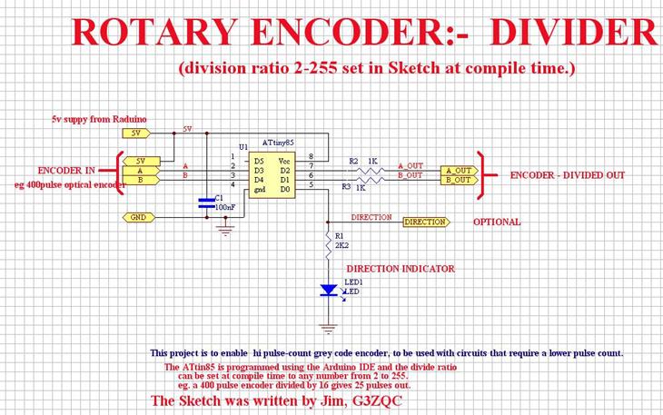
The “direction” output shown in the schematic, has not been coded but would be a very simple addition to the Sketch. This could be useful in projects where only direction and a pulse stream are required, not the quadrature pulses above. Simply use one of the outputs plus the direction pin.
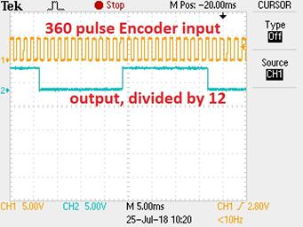
This picture shows input pulses in the top trace from a 360 pulse per tune encoder when rotated at a medium speed. The trace below is the output, divided by 12 in this case. (count the pulses to verify!)
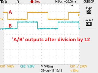 Here you can see both outputs after the division by 12. Here you can see both outputs after the division by 12.
Note the quadrature relationship of the Encoder input is maintained in the output.
THE SKETCH: Updated Jan 18th 2022. Pin allocation now agrees with the Sch.
If you download and use this Sketch, we would appreciate feed back on your results.
Quad_div_fsm_2.ino *** (includes direction output also.)
Sean sent me an email with a very interesting use for the Divider sketch. Sean reports:
Hi Glenn, I have successfully used the Sch and sketch on this page.
In a 2 factor quadrature divider between a Mitutoyo and a Mitutoyo DRO (dig. read out) intended for use with lower-precision scales. I got a good deal on the hi-precision linear scale but my DRO was double-counting all the distances. I tried a few things to halve the count before stumbling on your web page. Took just a few hours to make.
I did want to report a difference in the pin assignments (now corrected, above). Also it took me a bit of head scratching to figure out that I had to set the HALF_STEP flag in Rotary.H to get the correct factor. But otherwise it worked like a dream. <I didn't have to do this in my application, so not sure of differences, Glenn>
Sean Jan 16th 2022.
Glenn – vk3pe
Jim – g3zqc
Page created July 24th 2018, VK3PE
Last updated on
January 18, 2022
|