SWR & Line Current Meter
I was looking for a cheap and easy way to measure the output power of my 150W PA (by G6ALU) and this project seemed to fit the bill, measuring up to 5 amps peak although 3 amps on a continuous basis. Assuming a very low SWR or 50R dummy load, power can be estimated to be I^2 x 50. eg. 3 amps equates to 450W.
This SWR and antenna current meter appeared in a recent issue of the Australian "Amateur Radio" magazine. (April 2008) and seemed to fit the bill, especially since I had a couple of suitable meters to hand and the other parts were few and easy to find locally. The article is by Drew, VK3XU, who is a prolific home brewer and writer for our local magazine.
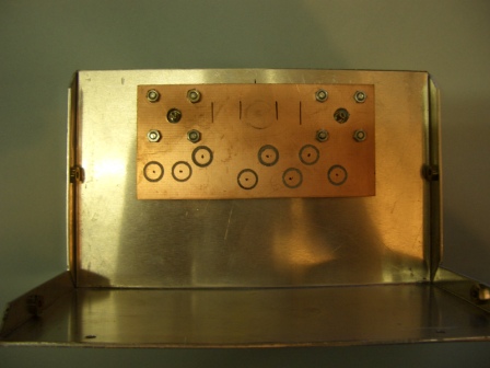
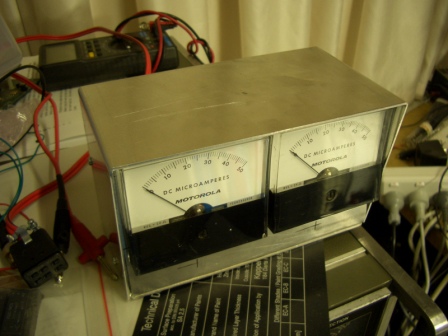
In the spirit of DIY, a home brew case was made from some aluminium sheet in three parts, front, base/rear and top cover. There are very few parts in the project and the original used a piece of PCB material with little round pieces of PCB stuck to it, to form isolated points for mounting the parts. I have an old spot weld removal tool and it removes a nice round circle to isolate a "pad". This was used and the circuit was quickly built. The "nuts" in the sides are thin sheet fasteners or root nuts. Found in a box at a Ham rally. It pays to look in all the boxes !!
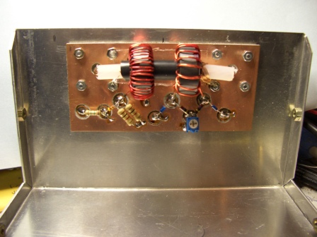
The trim pot is used to calibrate the SWR reading. There is one resistor missing on the right side connector. Toroids are a bit tedious to wind, with 40 turns on the left one and 13 on the other. The 40 turn toroid is used to generate a current of 1/40th of that flowing in the Co-ax cable. This current flows through a 470R resistor and a 1N4148 rectifies the voltage developed and feeds a 50uA meter through a 1.5M resistor. All quite simple but clever also, I think.
The SWR section on the right follows conventional practice and uses BAT46 diodes. A switch is used to select either the SWR or current mode on the right hand meter. Two SO239 sockets are mounted on the rear.
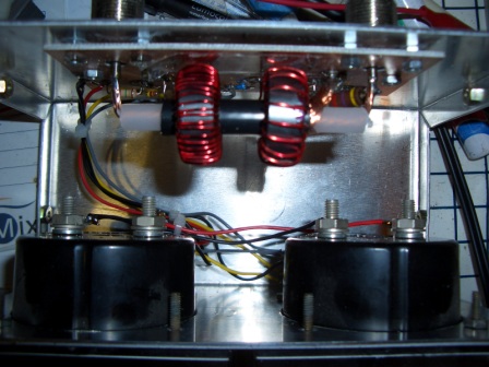
All wired and up and ready to test.
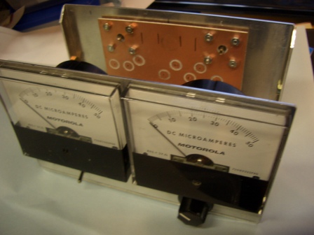
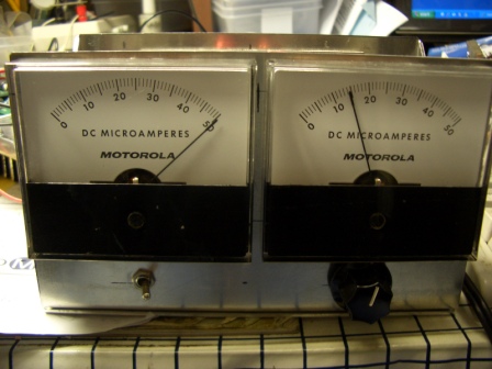
Here's the meter indicating about a 2:1 SWR. Left meter is Forward power while the right meter can be switched to indicate either REVERSE power or Current.
To the right is the finished meter. I may scale the meters later. I used some special semi-gloss grey sheet with adhesive rear to make a lable on a laser printer and gave the case a coat of grey paint from a spray can.

Actually, this little side project has spurred me on to make a decent dummy load. In fact, I might incorporate the current meter idea into the dummy load to build a direct reading power meter.
RS components have some nice non-inductive high power resistors. eg. 5 of the RCH50 S 10R in series would make a 250W load. They also have 100R 50Watt resistors of the same type for say a 100W load. (2 in parallel) This type of resistor requires a very good heatsink though to dissipate this kind of power. Perhaps fan assisted.
In hindsight, the above meter and load could have been built into a single case with suitable switching to select the load.
vk3pe
Page updated on May 26, 2008