LPF Construction
The LPF filter is NOT part of the official G3XJP PICaSTAR construction.
G3XJP did not prescribe any particular PA's or LPF's however this LPF has become the one of choice by majority of Piastar builders.
The documents, schematic etc for this build are on the G6ALU web pages. (Google "G6ALU LPF")
Draft Bill of material (BOM) 24-04-08
26th May, 2008 NOTE: the schematic lists sources for the Toroids and Mica caps that I used.
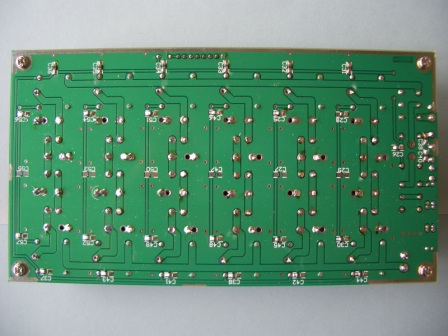
Component Overlays ( The ref numbers are reversed on each of the filters, compared to Ray's information on link above)
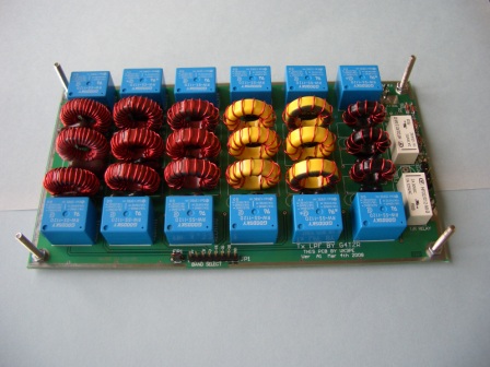
This page is simply the assembly and test of my own LPF board.
I bought all of the Mica caps and Toroids from the vendors shown on the schematic. Note that in some cases, you may need to parallel capacitors to make the required value. There is provision on the PCB for different pitch caps. and also large holes to allow paralleling them.
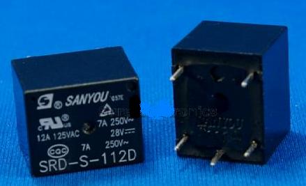
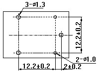
Typical relay data sheet for switching the filters (blue type below)
This will give you info on the dimensions etc for sourcing the relays. I bought 50 for about US$10 +post on Ebay (from "sureelectronics"). Check the vendors data against the above. Black type below.
(Cost has now escalated from when this page was origianlly written)
The small relays are Omron (or similar) type .......... See BOM and note below.
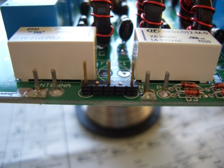
The RF connections on the PCB have 1mm holes. These are designed for PCB "pins" as below. The T/R & Attenuator control points have smaller holes and are on a 0.1" pitch. I fitted a 0.1" pitch header with 2 of the pins removed, as below. A mating socket will be used later for connections.
12th Jan, 2009: ABOVE. Be aware that if other than the specified Omron G5V-2 relays are used, the Attenuator relay MAY NOT operate. This is because some relay types/brand have a polarized relay coil. ie the voltage polarity MUST be correct for the relay to operate. The changeover relay is not affected.
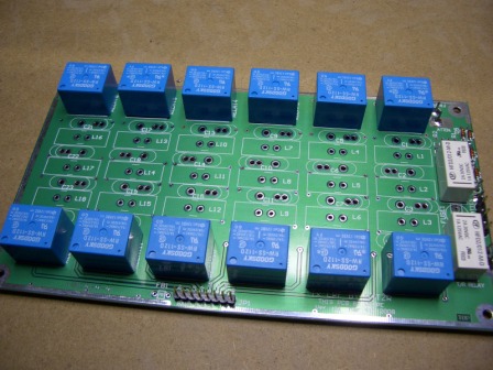
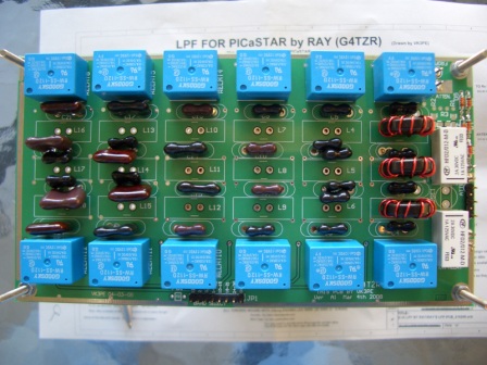
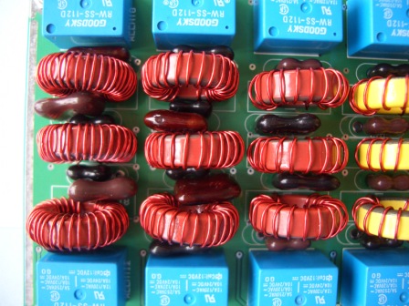
Below are pictures of the finished LPF board. Depending on what Mica capacitors you can get, you may have to parallel some values. It's a tight squeeze though, especially where the Mica caps are larger size. Insert all the capacitors for the band and the wound toroids, to enable you to juggle things about a bit, before you solder them!
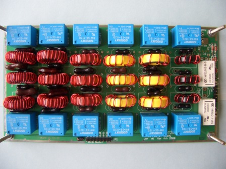
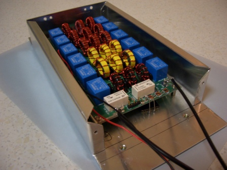
I fitted these temporary screws so that I could turn the assembly over for soldering, without damaging or moving any of the toroids.
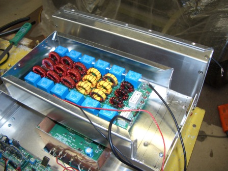
My LPF will be fitted in this home made enclosure. It will be hinged and fit on top of other blocks in the case. The end shown will have a PCB panel with feedthrough caps and co-ax connectors for interconnects.
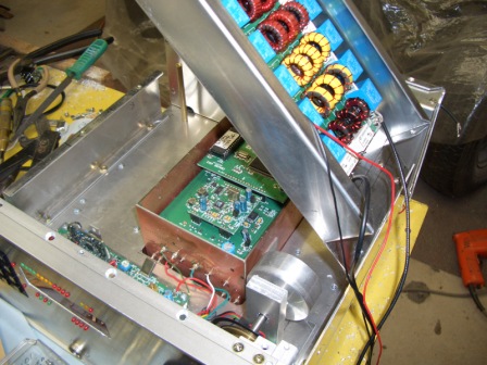
May 18th, 08 Lot's of work spent here making a shielded section for the rear PA compartment and also mounting the LPFas a hinged arrangement. Eventually the LPF will have a cover also and the open end will have a PCB section fitted to take feedthru caps etc.
The 20w & 140w PA's are fitted in the shielded compartment at the rear.
Does it work! ...........YES.
I have checked all bands and the filters are basically working, but I need to do a detailed check of losses etc.
8th May, 2008: More testing !
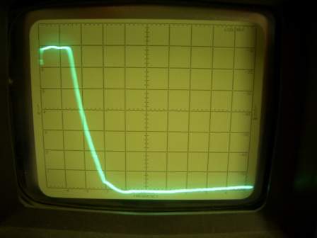
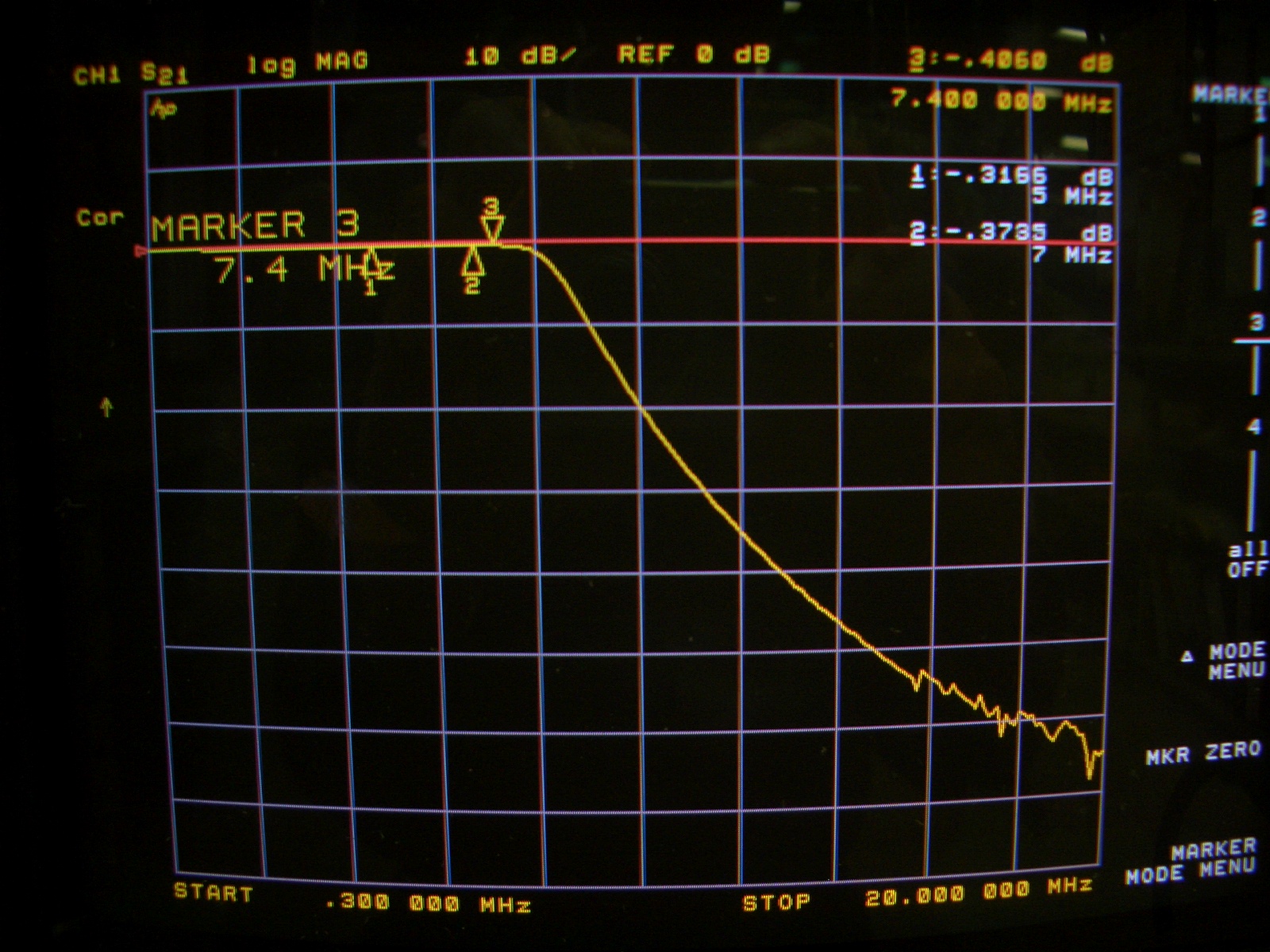
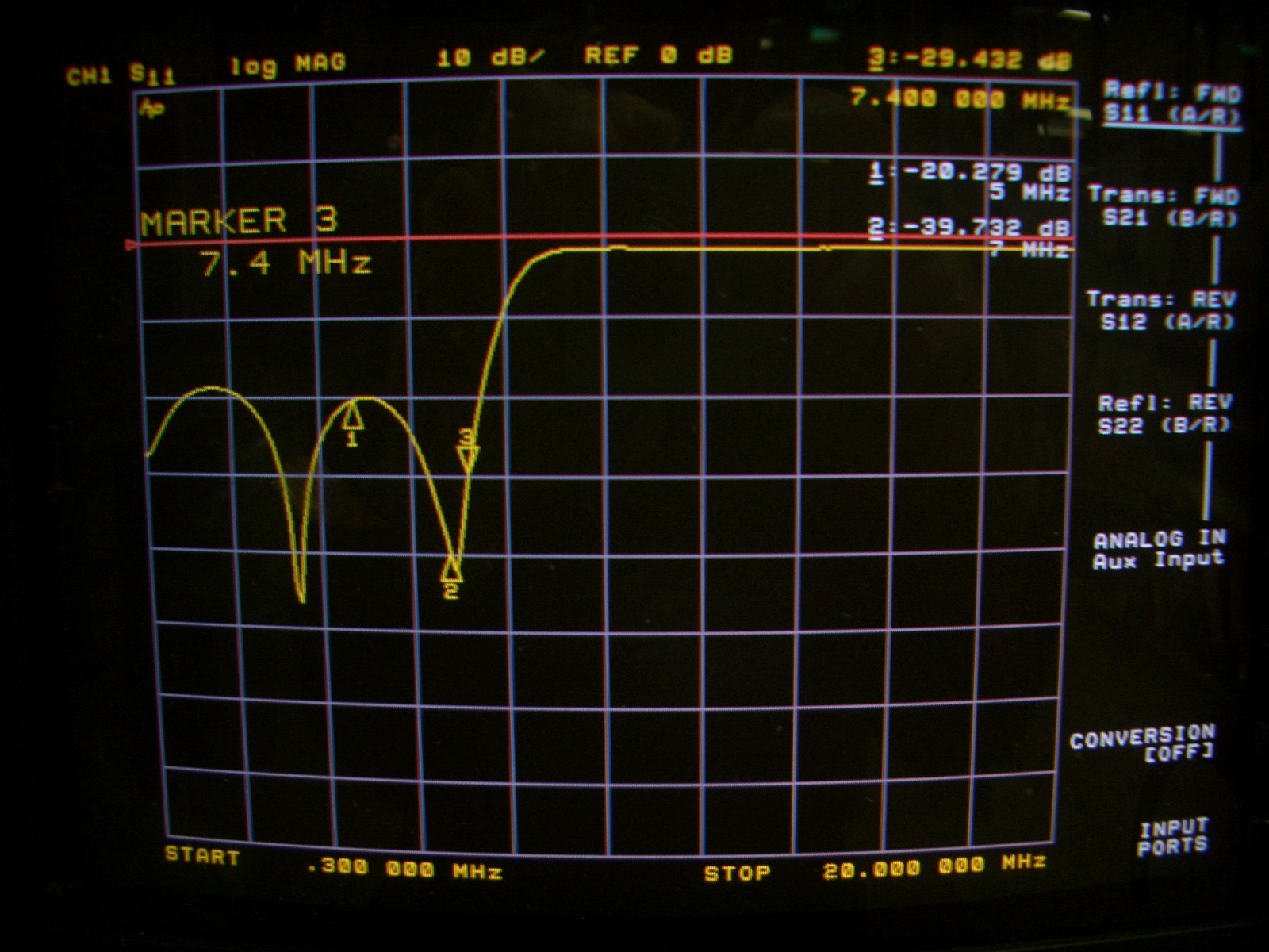
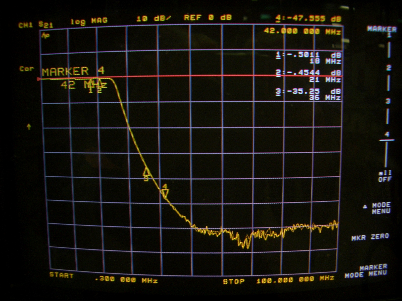
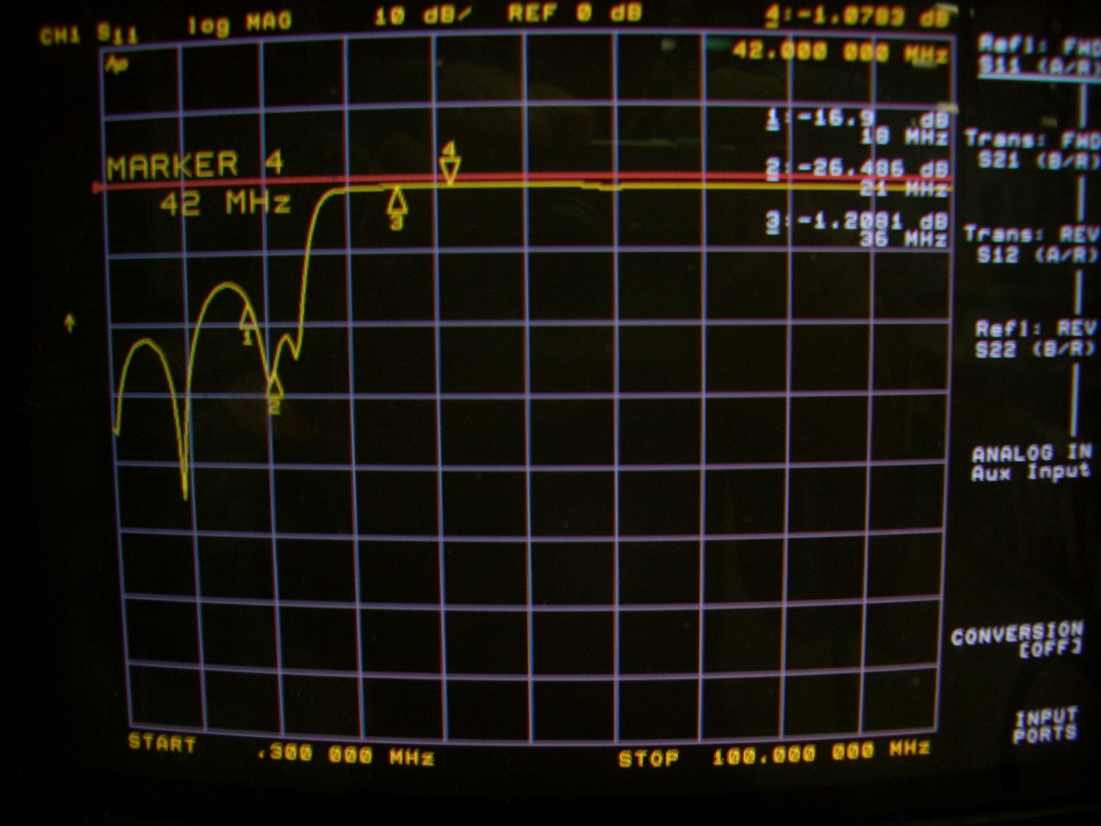
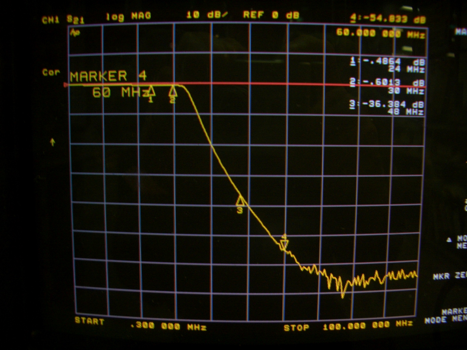
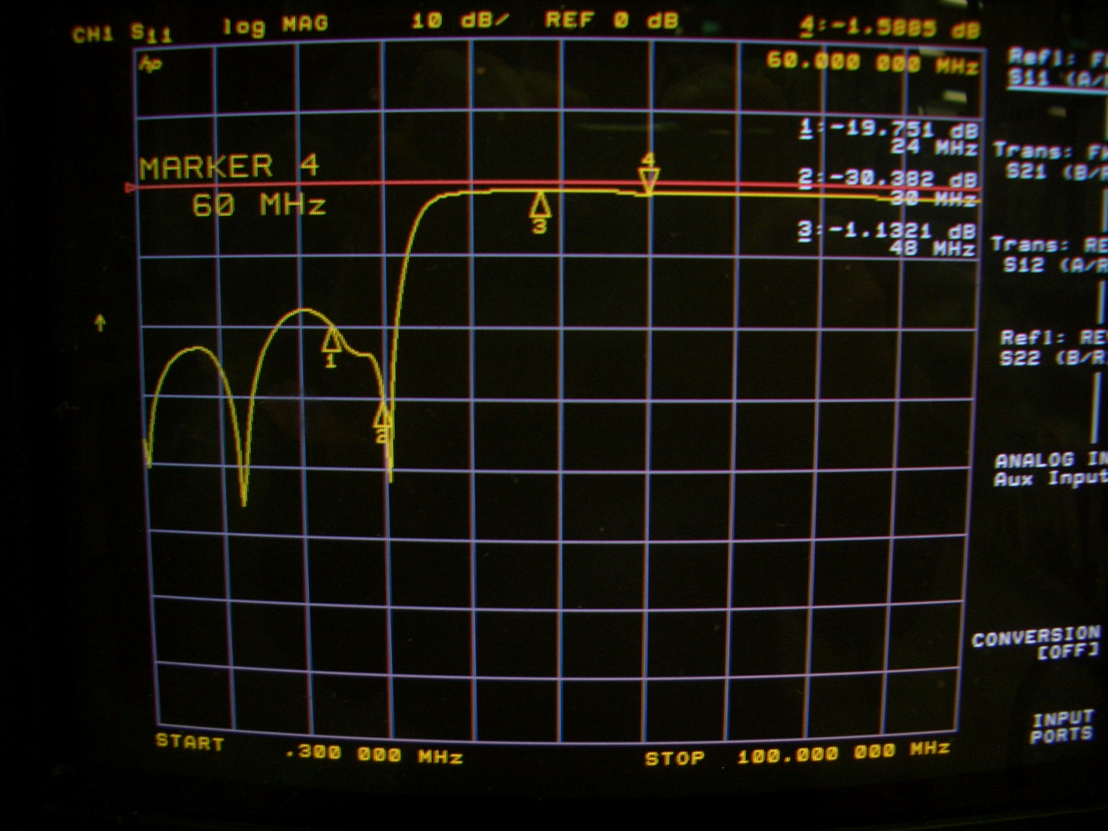
These pictures show the results of my testing of my LPF. Yours may vary, due to winding variations of the toroids and capacitor tolerances.
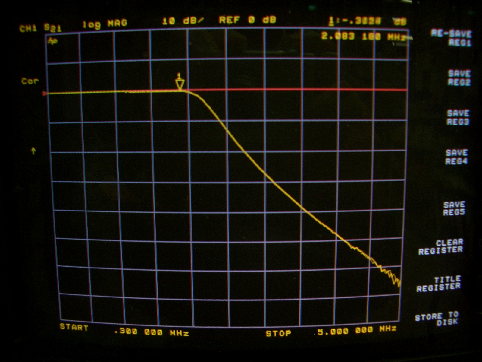
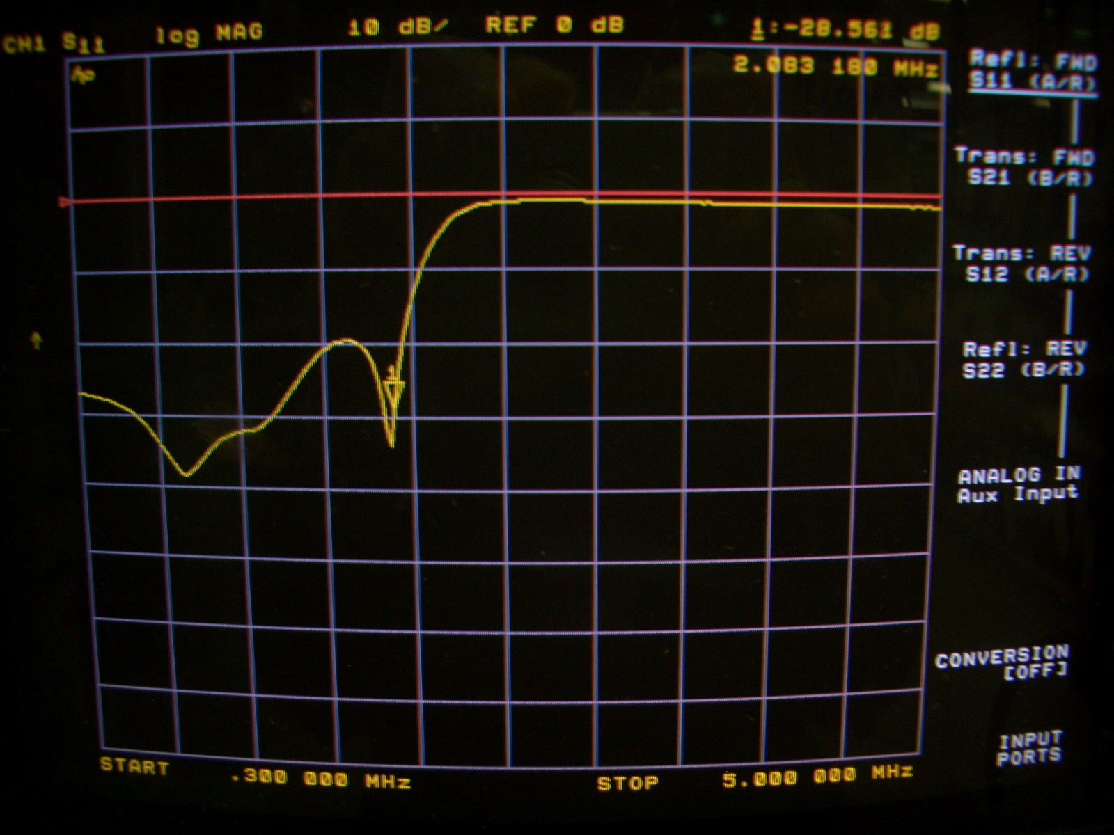
Left picture in each case is the response, right picture is the return loss. Response or in-band loss will actually be slightly better than that shown, as cable losses to the Analyzer (HP8753C) have not been taken into account.
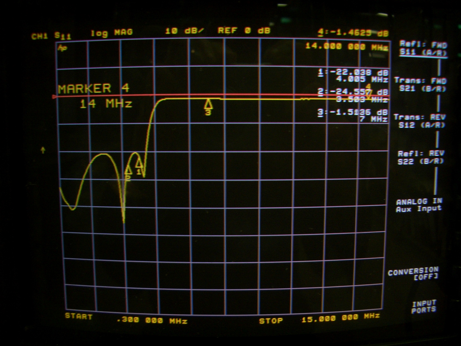
The little arrows are "markers". To the right, you will see the frequency and loss etc for each of the markers. They are generally at band edges or harmonics.
Click on picture for LARGER version
2MHz
3.8MHz

7MHz
10-15MHz


10 - 21MHz
24 - 30MHz
18th May. I now have the 150W PA tested and looking good.
VK3PE
Page created on 24-04-08
Last updated on February 6, 2019