Mats SM0RJV version of STAR
page created on 22nd Aug, 2008
Last updated on January 5, 2015
Updated on 4th Jan, 2015
Mats has now finished his Star, all home built PCB's and many re-designed, to suit parts to hand and also to incorporate Mats ideas.
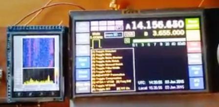
Also, to top that off, Mats has also built a colour TFT Panadapter for his Star using the "ChaN" DSP code available on the web as a basis.
Mats will be supplying some more details of his Panadapter soon.
.
050115
Hi Glenn, sorry but that was more pictures and text than I initially thought.
I hope I have not swamped your mailbox completely...
It has taken me quite a few hours to find all those old pictures but it sure brought up fine Star memories. I hope you received them without problems.
Regarding the panadapter, I think I will put together
a small document with my info/ideas rather than trying to type on the fly! Just
a quick reply to your comments on the list: Since ChaN has done such a great
job already it felt very natural to re-use it and just changing the display.
(from mono to full colour TFT) By replacing his "plot bars on display"
with a "send bars through serial port" subroutine one does not have
to redo any hard work, just some routines to show the data in a nice colourful
way similar to HDSDR or SDR#. And you are right, parallell interface is required
for speed! I have managed to keep a refresh rate of 50Hz or so, that would not
have been possible via SPI.
But more on all that later, I'll start putting a document together now!
73
Mats sm0rjv
<< Link here for Mats Panadapter information, when available >>
1
I had problems sourcing the Honywell optical encoder but found a kit of disc
and electronics by Sharp at Conrad. Some logic was required to convert quadrature
outputs to the pulse and direction format required by PnM which I included on
the PCB. The kit has unfortunately become obsolete by now.
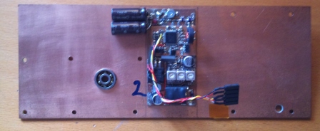
2
I made a small DDS assembly containing a Butler oscillator at 140MHz, heater,
tripler with 420MHz helical filter, DDS, LPF, and an ERA-5 output buffer amp.
This was fitted on the inside of the front panel assembly back cover.
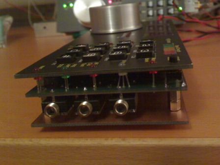
3
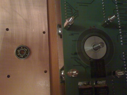
Here is a close up photo of the front panel assembly. Two 3.5mm connectors for
PnM, one for PicSWR.
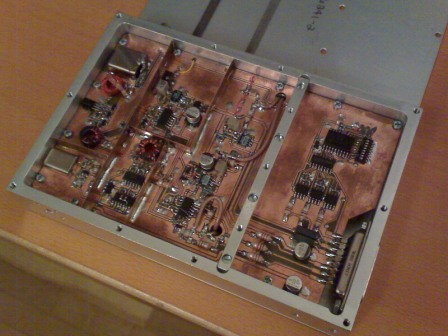
4
Apart from the PnM front assembly, each of my two stars consist of two identical
double sided milled aluminium modules that were available to me at the time.
They are 150x100x24mm in size and since there is a cavity for a PCB on each
side there is only 8mm of height available between PCB and lid. Module 1 contains
the IF and DSP, similar to the IF Brick in the Star articles. This photo shows
the IF board but also the Timer circuitry as can be seen on the right hand side.
In the upper right corner you can see half the crystal filter, the other half
is protruding into the other side of the module (see next picture). Apart from
being the only way to fit the filter in a thin module like this, it has the
additional benefit of providing very good stop band attenuation!
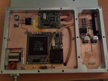
5
This is the DSP side of module 1. The cavity for the PCB is smaller on this
side, so on the right hand side it is actually the bottom side of the IF board
that is seen. The 10V regulator fits nicely there and the four pin header is
for in circuit programming of the Timer PIC. At lower left corner is the other
half of the crystal filter with its associated matching, shielding, and SMA
IF IN/OUT connector.
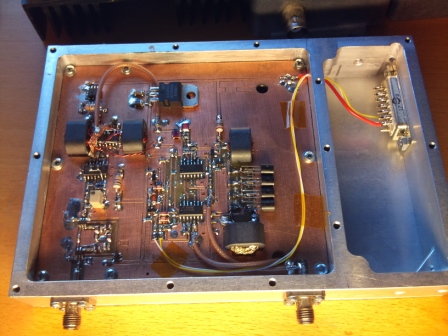
6
This shows the MR side of Module 2. Left hand SMA connector is the LO input
and just above it you can see I also added the LO filter (using solid state
switches instead of relays) on this PCB. Right hand SMA is the IF IN/OUT signal
that connects to Module 1. The RF IN OUT signal is in the thin coax that can
be seen disappearing through the hole in the PCB. It then connects to the BPF
PCB that is fitted in the cavity on the other side of the module (not fitted
when this picture was taken).
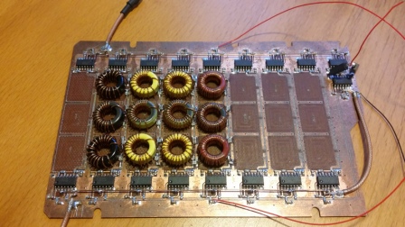
7
This is the BPF PCB that fits in the larger cavity of Module 2. The low height
forces me to use toroids and they are tuned by spreading/compressing the windings
while measuring the inductance. I use a VNWA for this. I measured and modeled
the MUXes and their surrounding circuitry, just for fun. The original filters
has no shunt caps at the input and output of each filter. As it turns out they
can easily be redesigned with same or slightly better performance with those
caps added to the filter topology. If at least 50pF is used during this redesign/optimization
(I use Microwave Office) it corresponds nicely with the stray caps from the
FST MUX:es and can be subtracted before fitting. The result is a thru-board
filter response more or less identical to the calculated filter. Not at all
required, but great fun to do!
8
A housing was made of PCB pieces. DDS assembly can be seen, and the three slots
to the left are for the 3.5mm serial comm connectors.
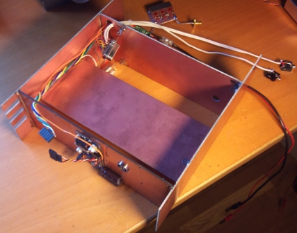
9
Front and housing with modules fitted. Module 2 (MR/BPF) and LO coax from DDS
to MR visible.
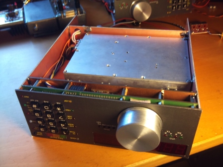
10
Front and housing with modules fitted. Module 1 (IF/DSP) visible. A small piece
of foam squeezed behind the tuning knob provides proper friction to shaft for
"good feel" while tuning around.
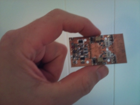
11
I designed a small broadband PA, here seen without transformers fitted. Sorry
for poor picture quality but it is a good size indicator :-)
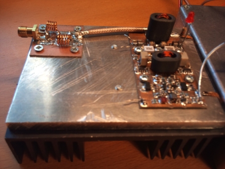
12
Here is a slightly better picture of the completed PA. By using 2GHz unmatched
28V LDMOS transistors and very carefully designed transformers this three stage
PA has flat gain (45 +/- 0.3dB), power (20W PEP), and IMD performance ( <
-30dBc / -36dB PEP ) from 1.8 to almost 200MHz :-) So far I ended up using it
with my 145MHz transverter rather than integrating it into Star and you can
see the 2m LPF in the upper left corner.
Glenn,
A few months back(2008) I got an opportunity to get a set of "professional PCB's" made for free. An opportunity to good to refuse, so I finalised the PCB layouts for PnM, DSP, and Codec boards. I made my own layouts simply to fit the components I have available, which means mostly 0603 size etc.
The rest of the STAR PCBs have also been (or are in the process of beeing...) re-artworked to suit "my" component sizes and mechanics. They will be "hand made" though. A short description of each picture follows;
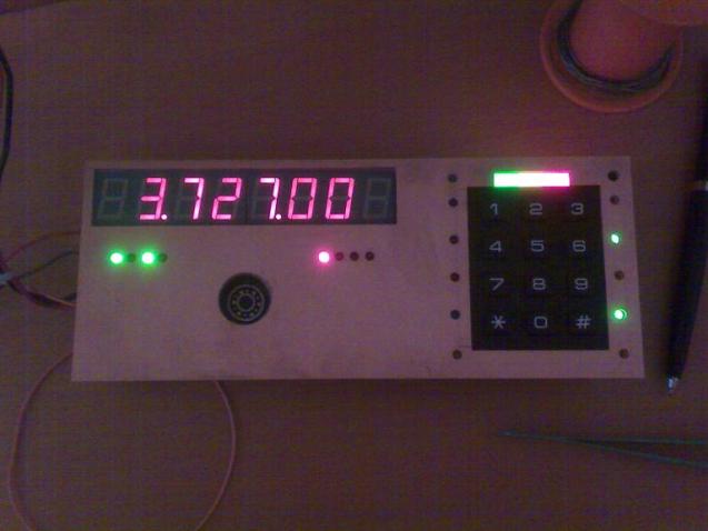
"DSC00070.JPG" PnM Mk1 many years ago!!! Actually very useful to get familiar with UI and handling ;o) Not seen on picture is the modified mouse (!) I used as a tuning wheel...
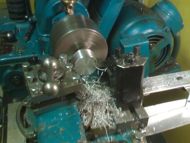
"DSC00078.JPG" Tuning knob in the making, from solid aluminium. Life is easier when you have a friend with a lathe! I operated the lathe myself though.
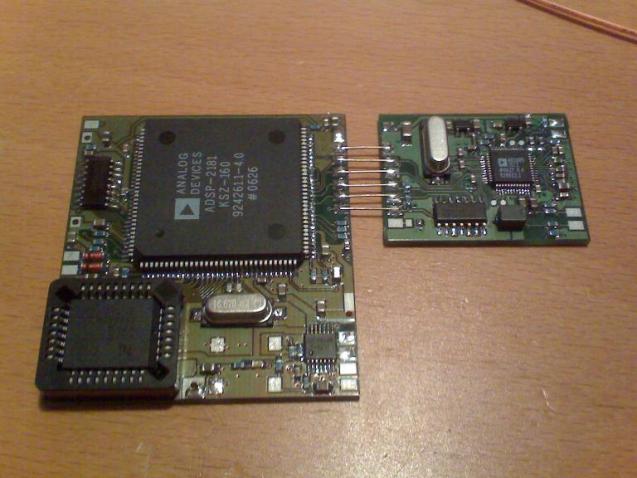
"DSC00082.JPG" My version of the DSP and Codec PCBs. All motherboard components but the 5V regulator has been put on the DSP board itself. I also replaced the DIP EPROM with a PLCC Flash EEPROM (can be found on a many old PC motherboards). Reset and Int switches not yet fitted..
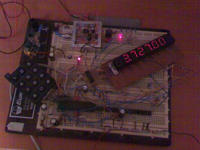
"DSC00083.JPG" Early test of how the mechanical parts fit together. Note that I use two "quad" displays because I happened to have them...
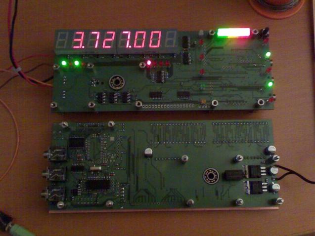
"DSC00084.JPG" My two PnM front assemblies seen from both sides with front panel and keyboard removed. I put pretty much everything on one board with components on both sides, i.e. PnM, status, and Picswr. Therefore three 3.5mm jacks that connects to the PC can be seen. I kept all serial buses at TTL levels on the board to avoid the MAX232 and its switching voltage converter. Instead I use a "USB to TTL cable" from FTDI. The picswr pic was not yet mounted when the picture was taken as can be seen on the lower board.
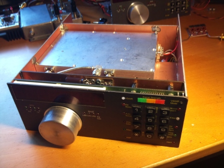
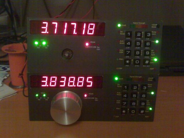
"DSC00089.JPG" Putting it all together and looking at the result is very satisfying! The front panels were made from self adhesive laser printable plastic and I really like the result. Since the picture was taken the second tuning knob has also been made. I'm currently working on the IF board, but available time is very limited. Will send more pictures as I continue finalising my stars later.
Thank you and 73s Mats SM0RJV