Viv's PICASTAR build.
Click pictures for larger size.
Date: Sunday, January 25, 2009 9:54 PM
Hi Glenn
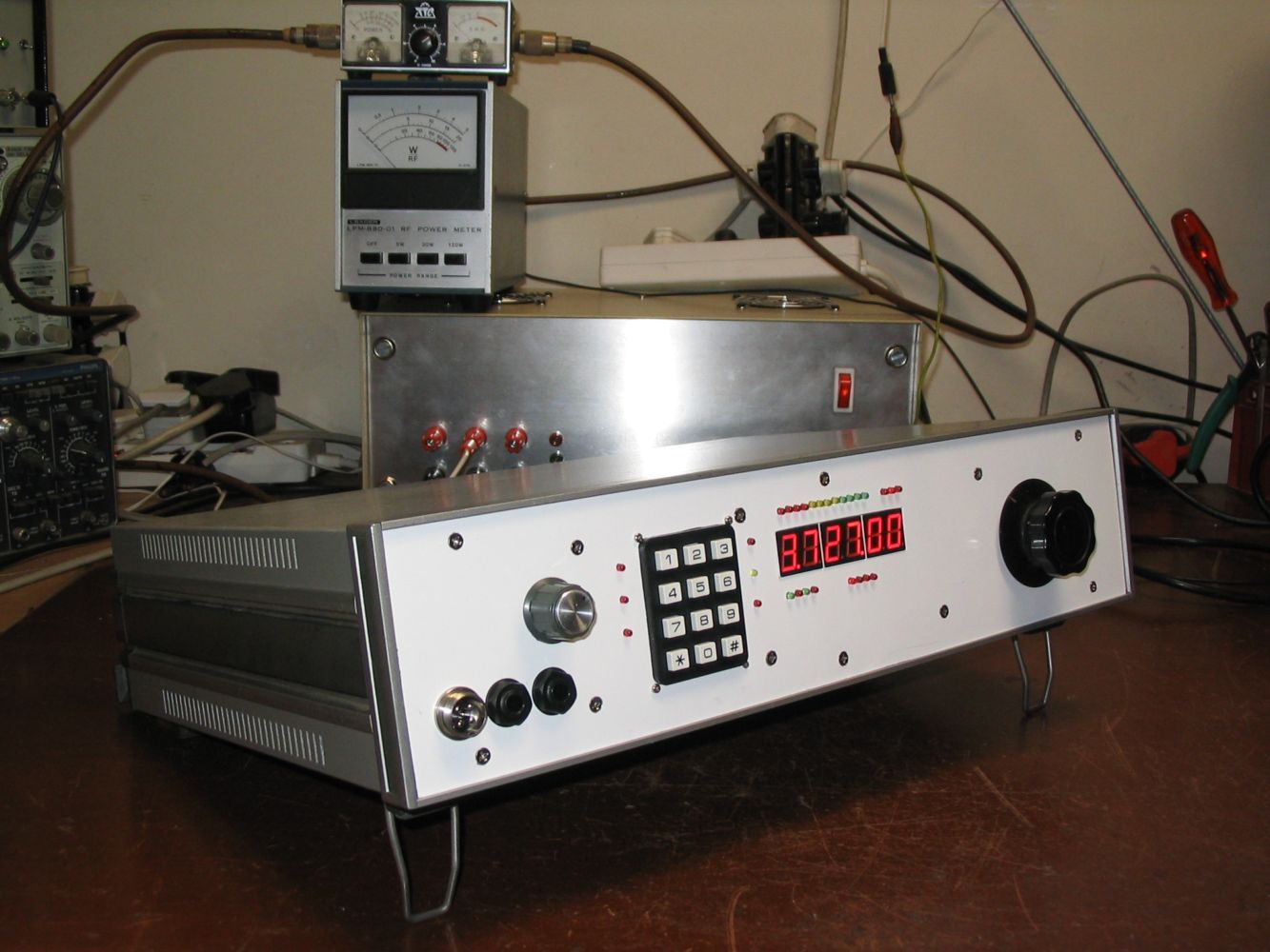
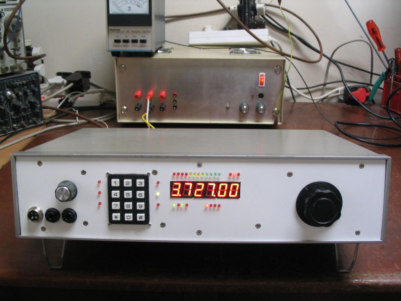
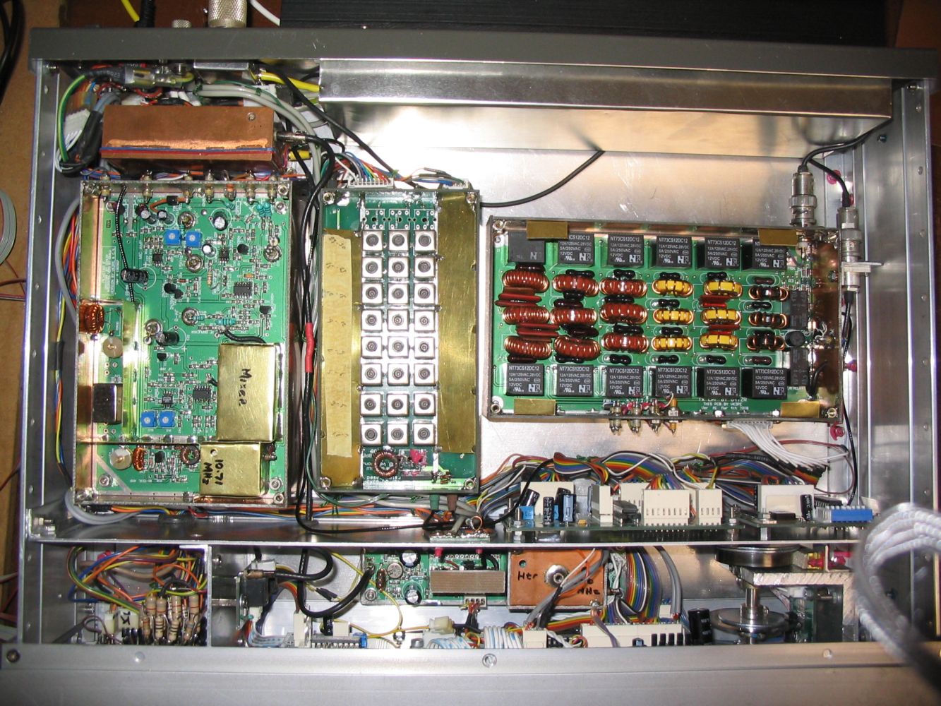
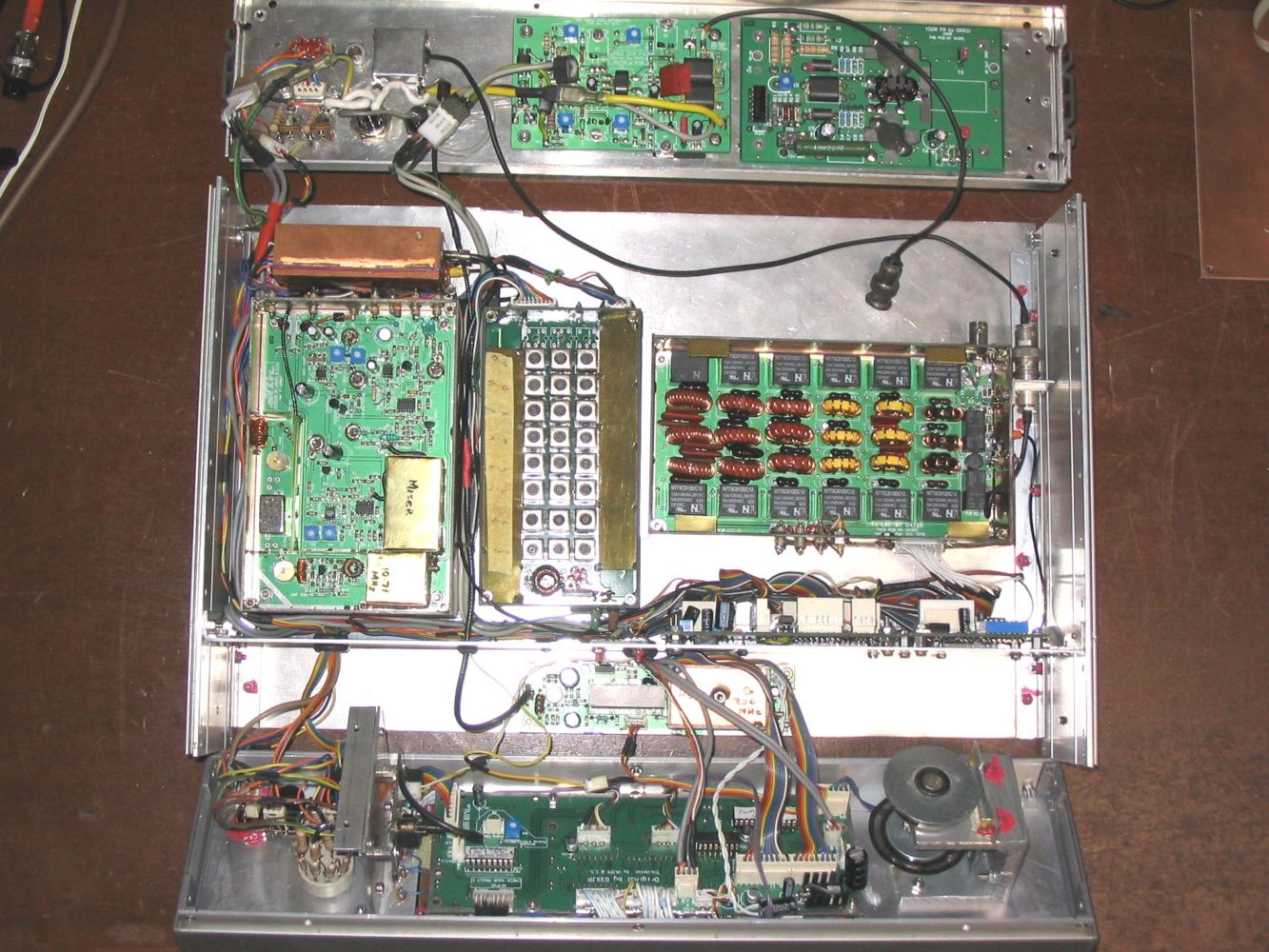
Per promise, attached pics show my build.
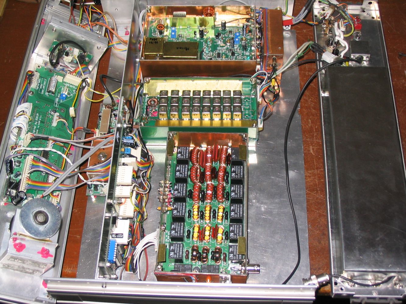
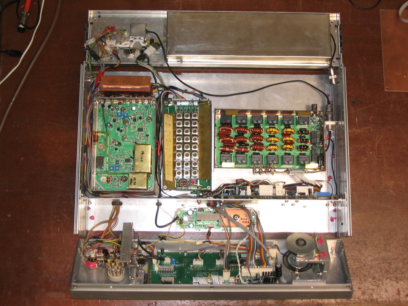
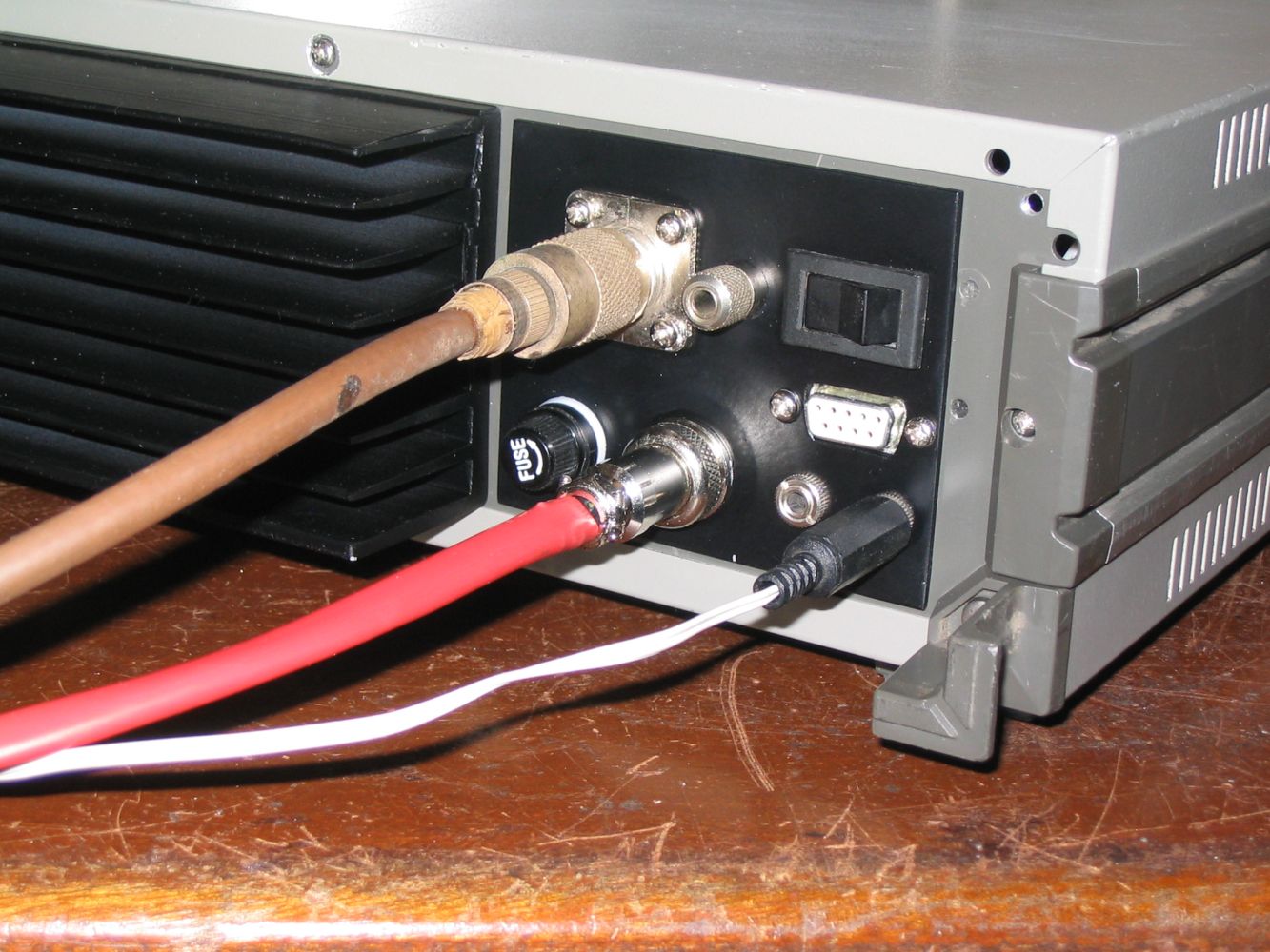
With the exception of the 150W PA it's fully operational. One of the pics shows where the 150W PA will go, inside the screening can. With just the 20W PA, on continuous carrier, it runs cools but I expect things to heat up a bit when the 150W PA is installed. I don't think that the heatsink will be enough for continuous carrier duty, but should be ok for normal amateur radio duty. You will see that my front panel has been stretched, and includes a headphone jack and headphone level switch (4dB steps x 6). My speaker outlets are single jacks, the RS232 uses a proper 9pin cinch, the internal/external control is selected by the rocker switch on the back by the RS232 connector.
Power is taken in via an 8 pin connector, four connections for the ground, and four for the 13.8. The 13.8 is split so that 3 of the pins carry power to the 150W PA, and one pin (fused for 4A) is for the rest of the set. This is to circumvent any power drop modulation effects that might be caused by the high current draw of the 150W PA. I'm still contemplating the fusing method for the 150W PA, a 20A (30A) internal car fuse might be a good idea. I figure that any excess current drawing failures by the 150W pa are likely to be terminal and will probably need internal work.
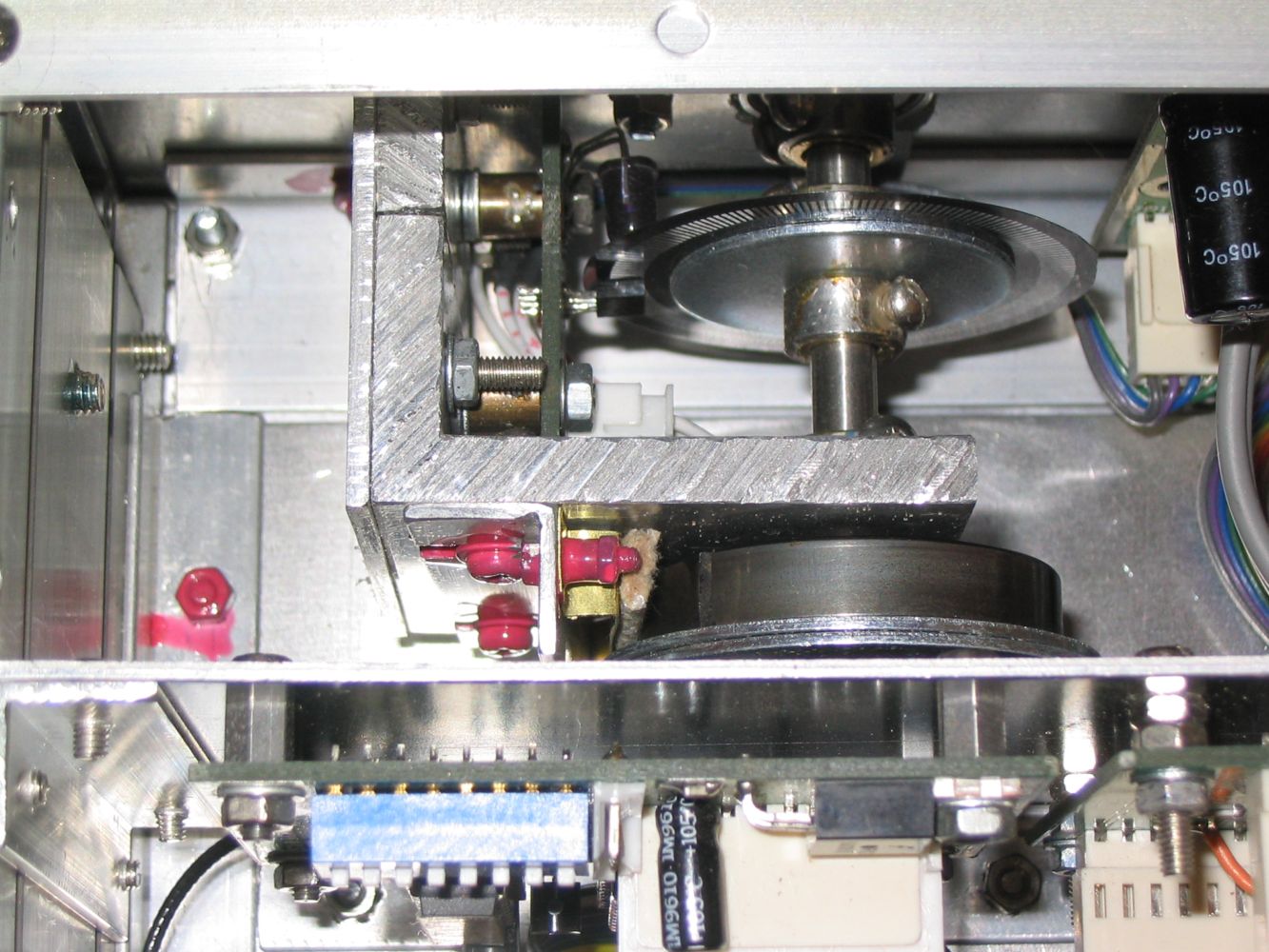
Every board and assembly can be accessed and removed on its own without a soldering iron. The cabling is such that any module can worked on whilst still connected.
I must say that it been an interesting project, with quite a lot of learning curves, it's taken me just over a year from start to finish. All I need now is an antenna.
Cheers Viv
Created on 27th Jan, 2009
Last updated on January 30, 2009