Paul, M1PVC's, PICaSTAR's
Not Content with building one Picastar, Paul (like many) has embarked on another build and as usual, has excelled himself in the details. Browse through Paul's pictures below. Some pictures can be clicked for a larger view.
Updated on 27th July with new pictures of P/S #2
PICaSTAR #2
Hi Glenn,
As promised herewith some pictures of my Star2 build.
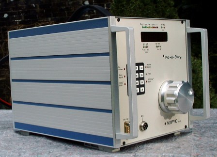
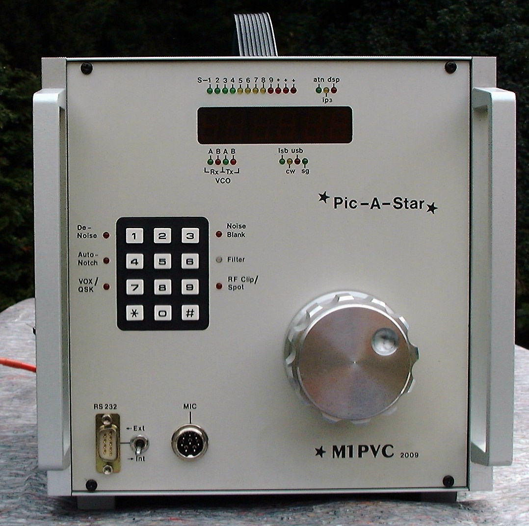
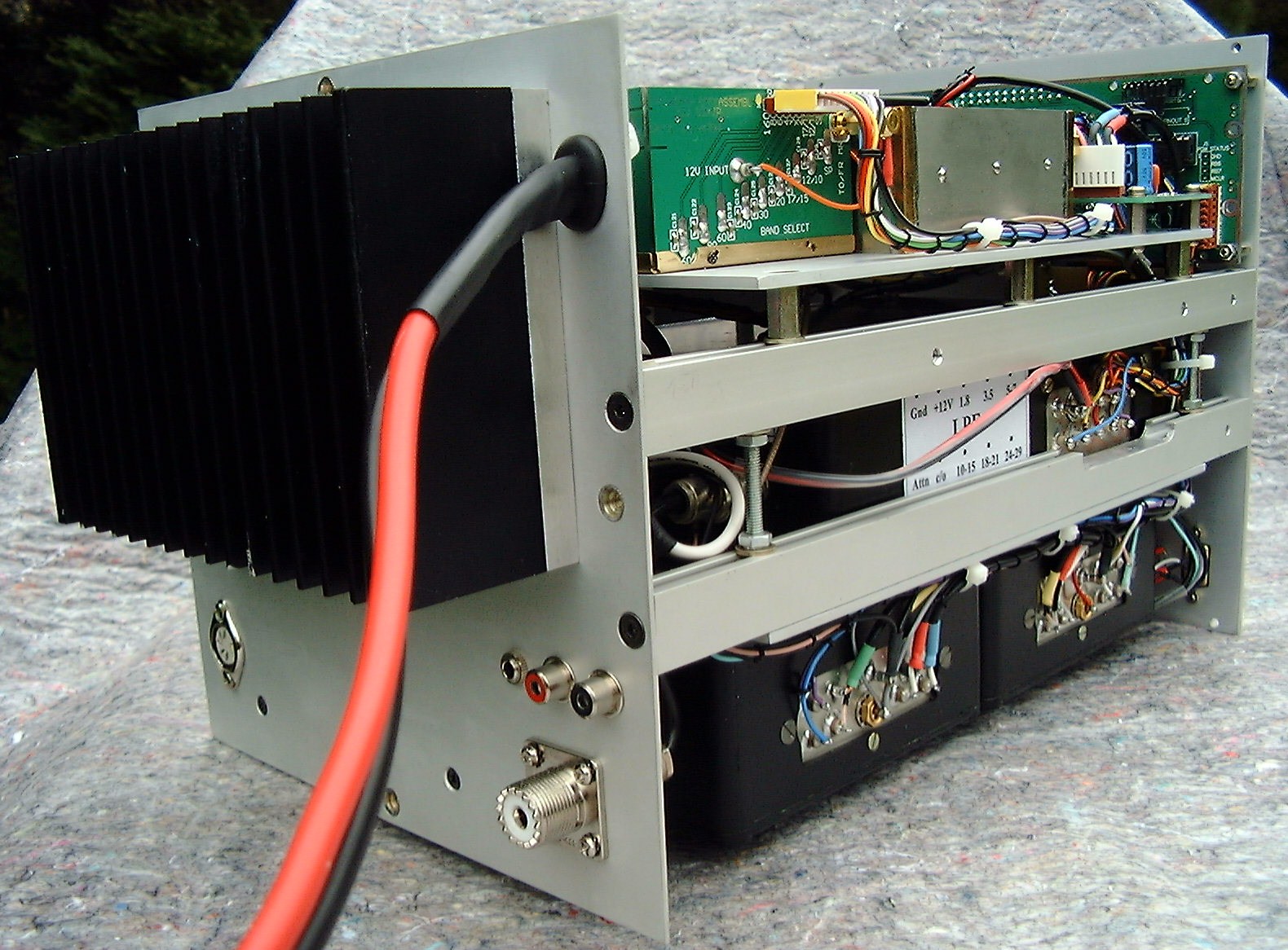
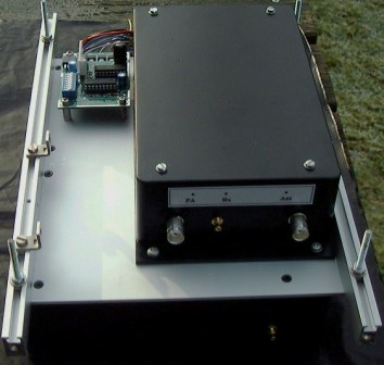
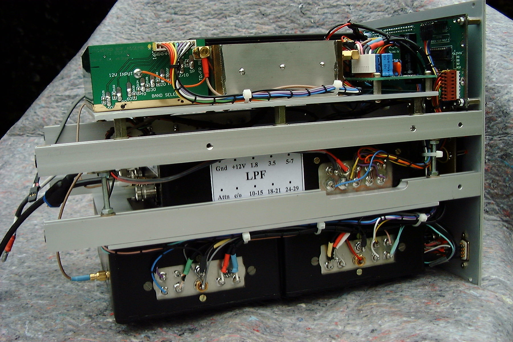
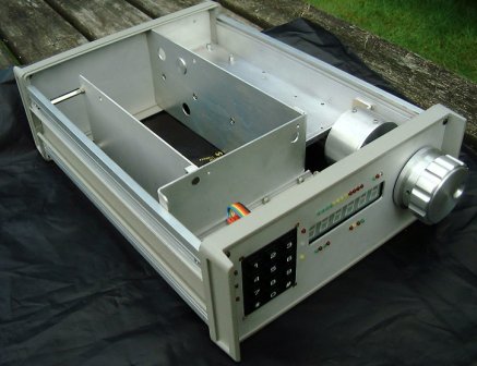
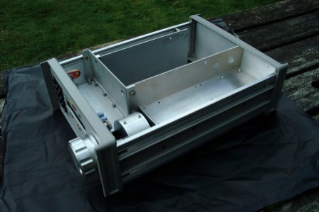
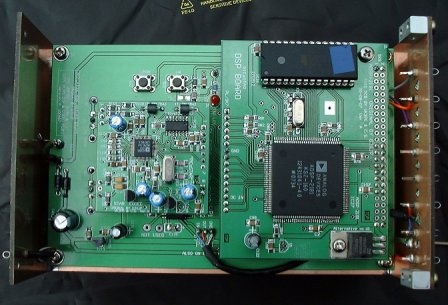
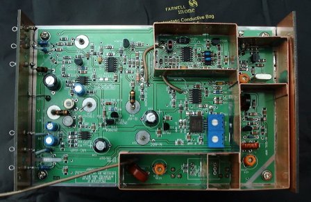
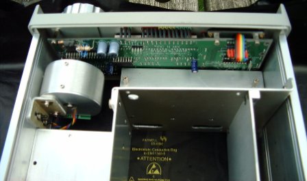
"My star2 is housed in a surplus aluminium instrument case measuring 205mm wide x 205mm high x 310 mm deep (just wide enough for the PnM board). The construction comprises 3 decks. The top deck holds the DDS (screened in a diecast box), the matrix/amp module, the MR and the BPF (screens yet to be fitted). The middle deck holds the LPF (in diecast box) and timer modules as well as a power distribution board with fuses and voltage dropping diodes (yes this time I have reduced the MR to 12 volts and the FET's are running cool).
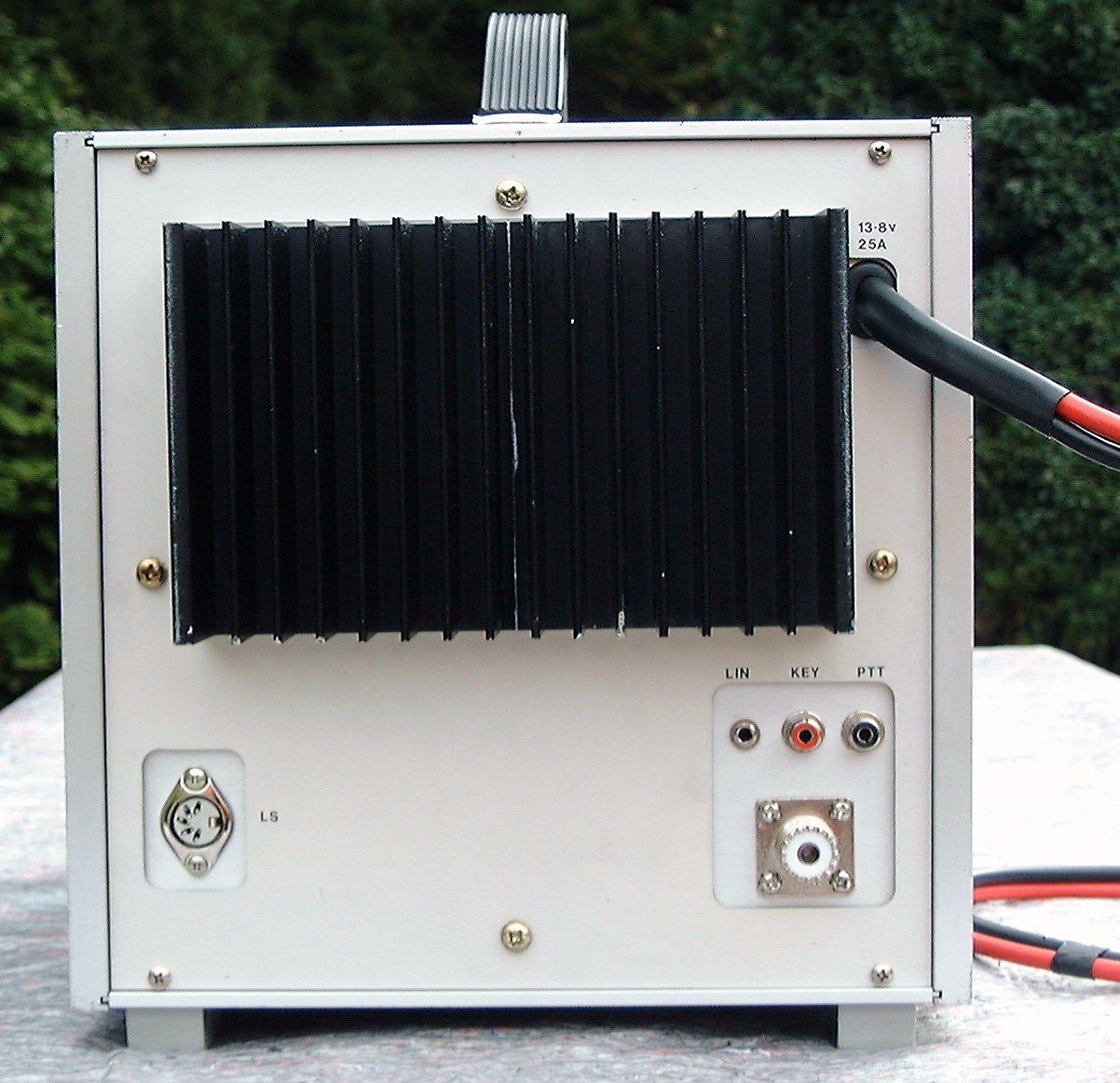
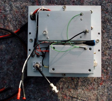
The bottom deck holds the DSP and IF modules each housed side by side in their own diecast box. The PnM and encoder are held on the front panel and the 150w PA and PA driver boards are held on the rear panel both in bespoke aluminium enclosures.
In the main all RF coax connections are terminated with SMC connectors using RG178 coax. Din connectors and RG58 are used on the higher power lines. Access for servicing is good for all modules that need measurement/adjustment."
Cheers Paul M1PVC
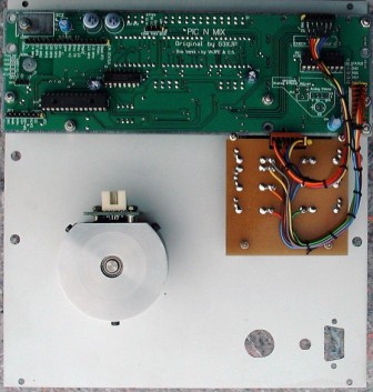

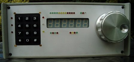
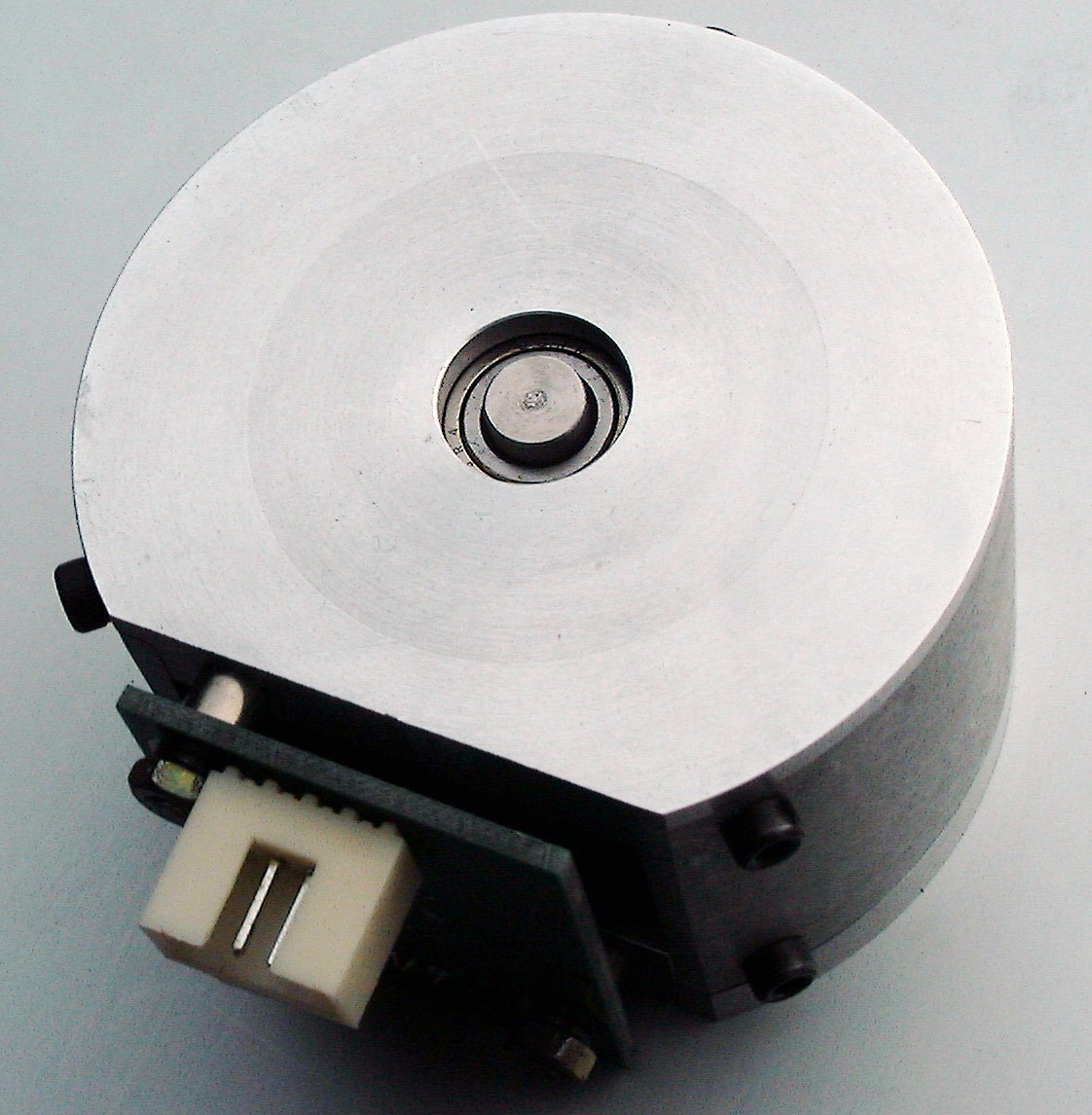 Encoder
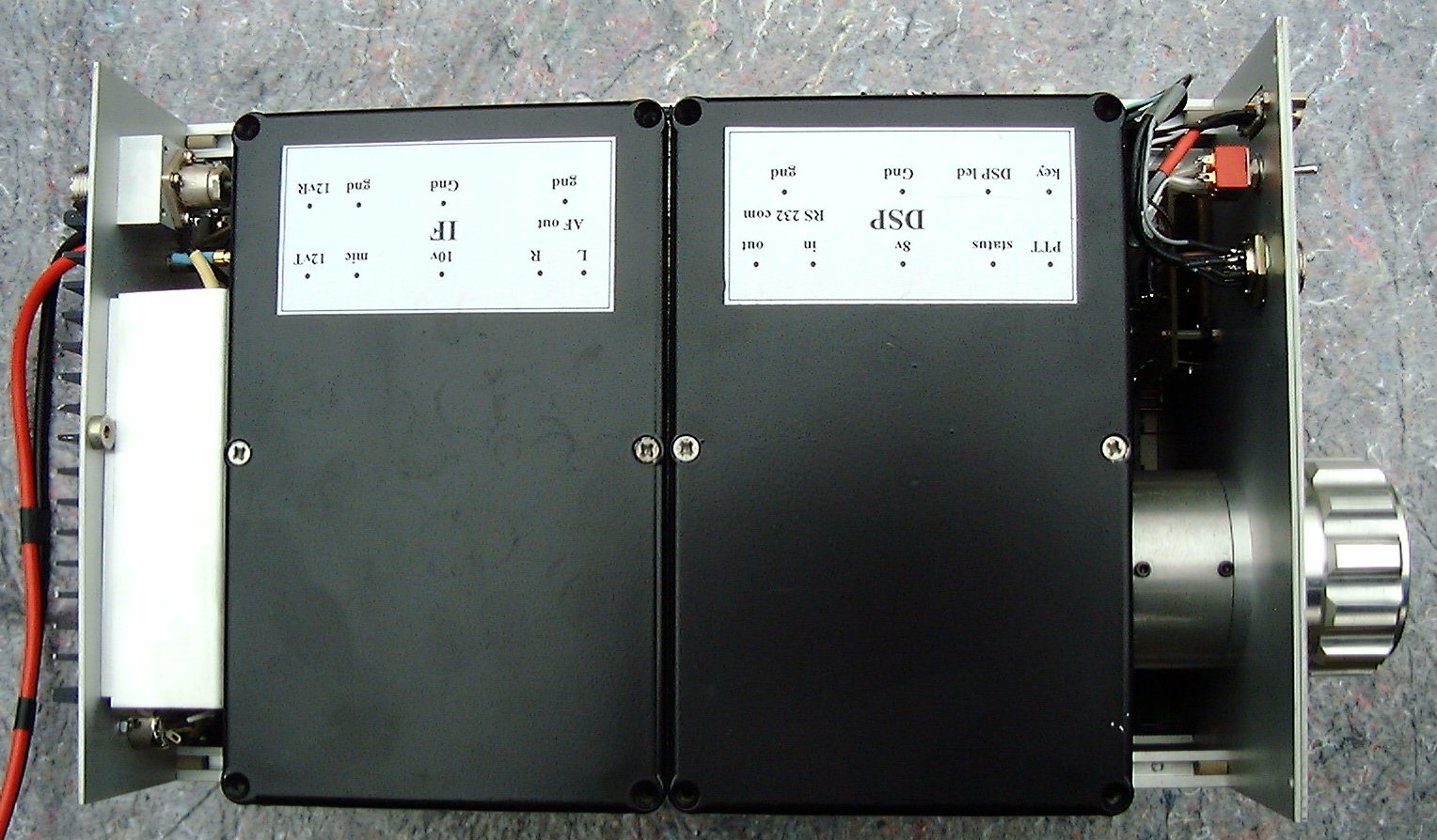
PICaSTAR #1
12th April, 2008: More home built STAR pictures from Paul, M1PVC
Hi Glenn, Since mid March I have been quite busy with the constructing.
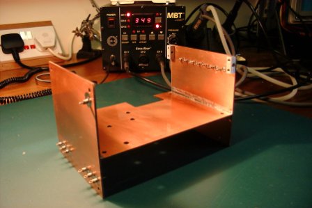
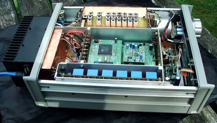
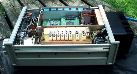
I found a metal instrument case in my collection which is only slightly smaller than Peter's PICaSTAR, a little narrower. It's proving to be a bit of a shoe horn job but at last I think that I've cracked it.
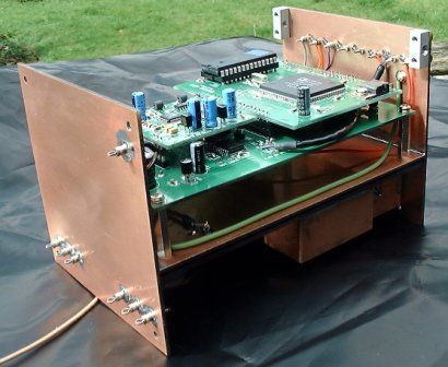
I have attached some photos for your information. Progress is as follows - All Glenn boards populated apart from 20W PA FET's The DDS carrier is complete but not fitted yet ( soldering that chip got me going!). Encoder constructed and tested OK - I am a model engineer with a well equipped workshop so I was in my element here.
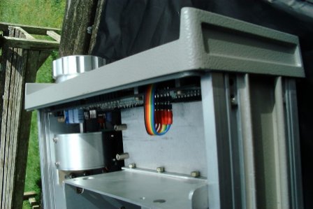
I also machined the aluminium/brass knob which also acts as a flywheel. The encoder runs with ball races back and front and a long bronze bush carries the shaft though the front panel and gives some slight friction to improve the "feel" DSP/IF carrier constructed from double sided PCB material and the Glen PCB's integrated. Case sub-divided with aluminium screens and partitions. The spaces shown left in the pictures are there to accommodate the PA and LPF Prior to receiving your boards, I had already constructed the 150W PA and the BPF modules. The next jobs are to carry out the inter PCB wiring, populate the rear panel, screen the Butler osc., complete the PA and LPF modules and continue with the testing and commissioning regime. All great fun but the Summer, holidays and the XYL will probably now slow me down.
Kind regards & 73 Paul M1PVC
9th Aug 2008. More pictures added below as Paul has almost finished the build.
.jpg)
.jpg)
.jpg)
.jpg)
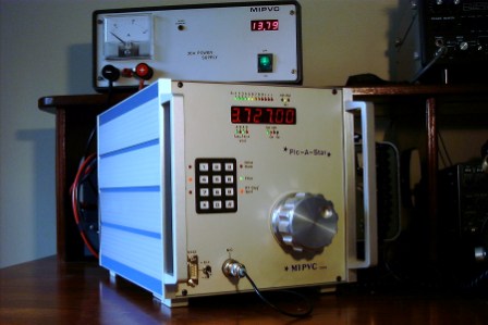
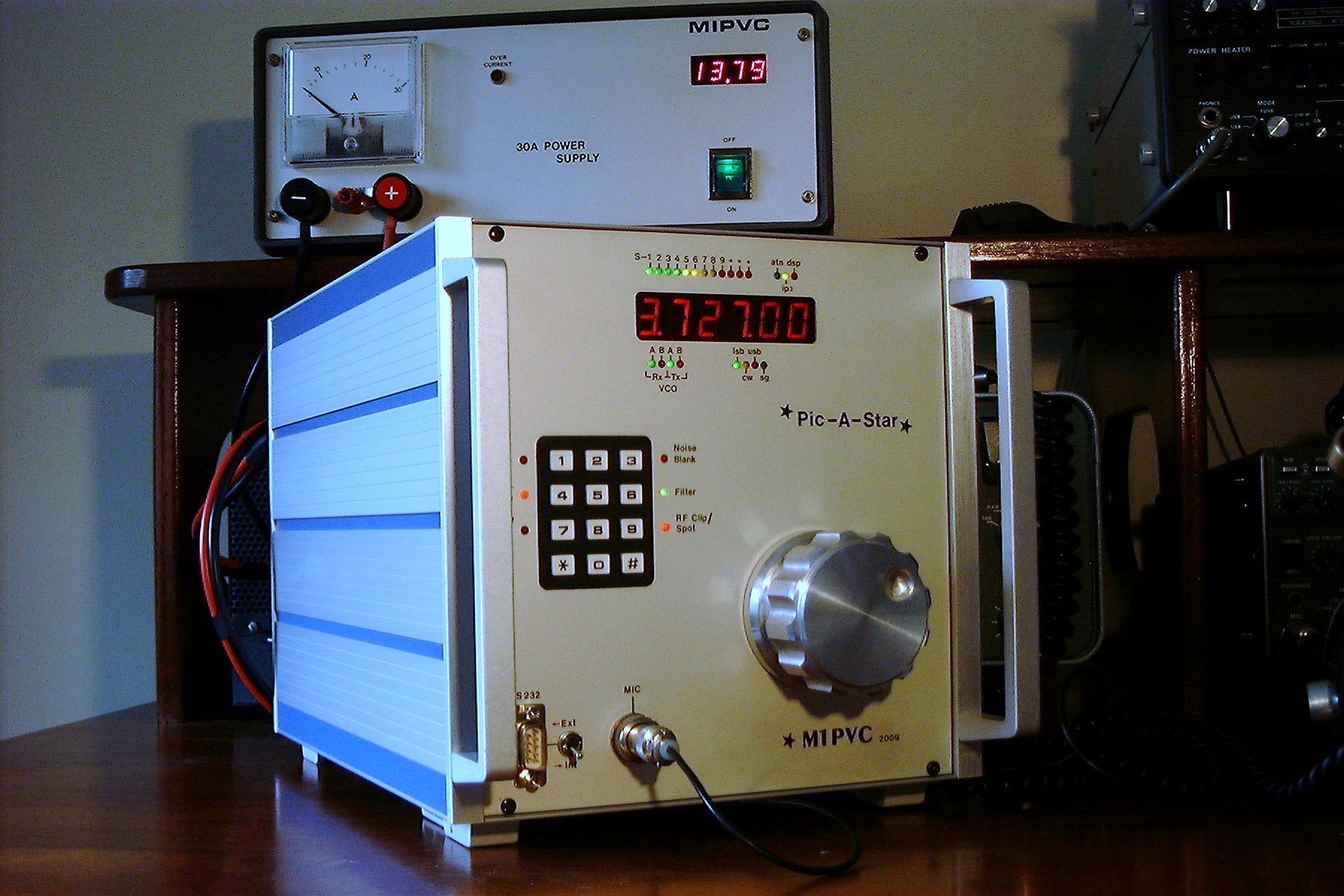
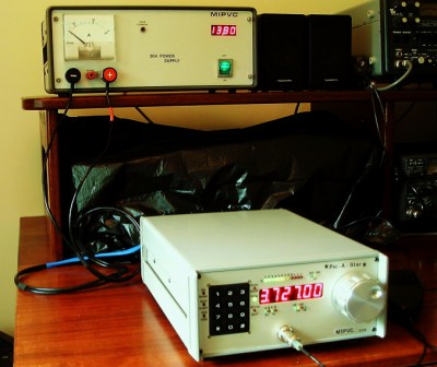
9th Aug 2008: Paul advised his STAR is almost complete and now has a G6ALU 140W also. (black box)
Paul also built his own 30Amp power supply in his spare time !!
 Great job Paul.
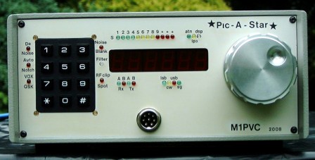
Update 27th July, 2009
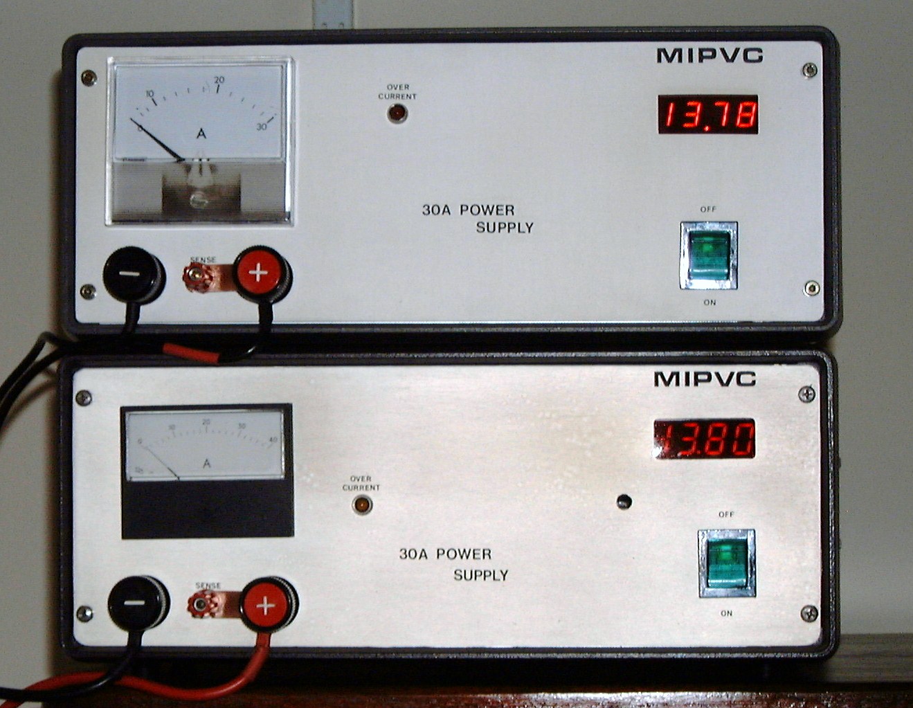
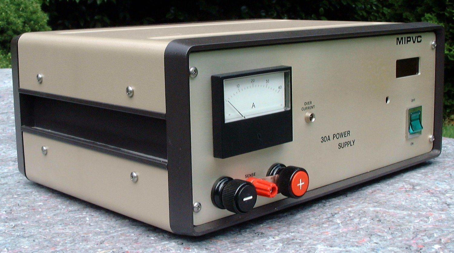
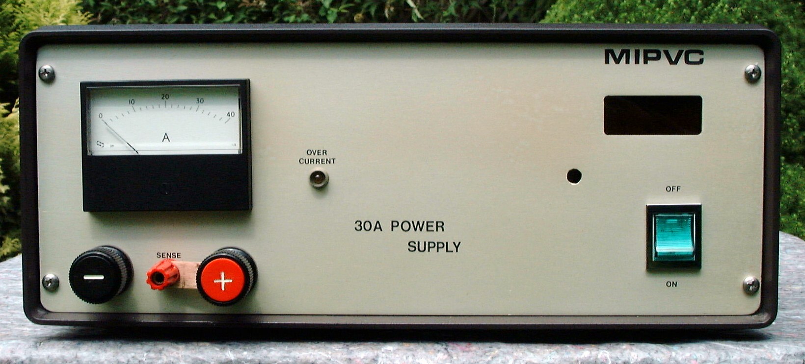
Always busy, Paul has recently built another 30A supply for his 2d STAR:-
Hi Glenn
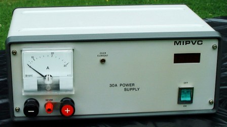
As requested, herewith some pics of my latest addition to the homebrew gear - "The 30A power supply was built to power my second Star.
Luckily I have managed to aquire an identical case (except for colour) to the one that I used on the supply for my first Star.
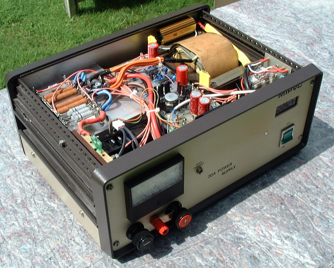
The transformer was salvaged from a Heathkit HP-1144 13.8v supply which I purchased at a rally this year for £15. The Heatkit supply was only rated at 10A continuous, 20A peak, but the transformer has proven to have good regulation and will run at 30A for 10 minutes without any appreciable rise in temperature - absolutely fine on SSB duty cycle at 150W RF output.
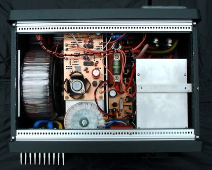
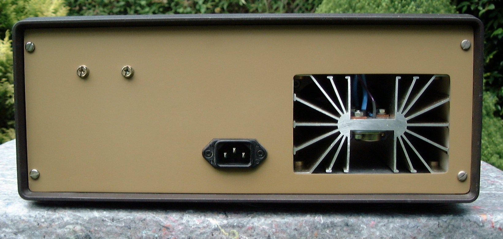
As before the supply uses the ARRL circuit from a 1988 edition of their handbook. It is overcurrent and over voltage protected and totally impervious to RF. I mounted the regulator transistors on a horizontal heat sink together with the 35A bridge rectifier. This assembly is enclosed in a "tunnel" and is cooled by two 60mm Papst 12v fans run at half voltage to keep them quiet. The fans run continuously at present but I may incorporate a thermal switch circuit to avoid running them when not necessary to aid efficiency. I have also incorporated a soft start circuit to the transformer primary to protect the bridge rectifier, etc. from the heavy current surge on power up due to the high value reservoir capacitor (100,000 uF).
The "extra" hole in the front panel is a product of using a salvaged sheet of aluminium which was areay drilled for a previous project. I will probably incorporate an indicator light here to give the fan status if I install fan control.
Kind regards & 73 Paul M1PVC
Click for larger pictures:

Hi Glenn
As I said in my previous e-mail, I made a number of changes to the '88 ARRL H/B design.
In the main these were -
1 - I used a different transformer with full wave bridge rectification. For both supplies this gave me a higher unregulated supply of about 21 volts on load. To cope I used 6 "pass" transistors on the first supply (cooled with one fan) and 4 "pass" transistors on the second supply (cooled with 2 fans). On both supplies I also needed a second transformer to supply the 15v AC required by the regulator board (this winding does not need to be anywhere near as high as the 1.5A rating that ARRL specify).
2 - I dropped the value of the reservoir cap to 100,000 uF as I had two of these in my junk box.
3 - On my second supply I have metered the current with a 1mA meter + suitable series resistor across R2. Saves finding a large shunt.
4 - The +V out and V sense terminals are bridged behind the front panel with a 10R resistor ( Supply therefore still regulates if external link becomes disconnected).
5 - My overvoltage crowbar would not fire with the 680R gate resistor. Reduced to 100R - perfect!
6 - R1 value changed to give a foldback current limit of 1A.
7 - 35uF cap on pin 5 of U2B reduced to a 22uF tant cap. Gives absolutely stable regulation over initial warm up period.
8 - Second supply fitted with slow start circuit in transformer primary (like valve linears) to protect bridge rectifier from switch on current surge.
First supply used a meaty 50A bridge well able to cope with the surge however without slow start mains fuse needs to be much larger. Also case metalwork should only be grounded at one point (reservoir cap neg terminal) to avois earth loops. Decouple across +V and -V terminals with 2200uF, 10nF, 100pF combination.
If you hear of anyone wanting to have a go at this design Glenn please feel free to circulate these notes.
Cheers Paul
July 30, 2009