Buzzer/Beeper page:
Last updated on November 16, 2009
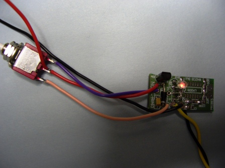
This Beeper is by W4ZCB The beeper is for safe testing of populated boards
The PCB was supplied as part of the Glenn PCB's on Panel #2
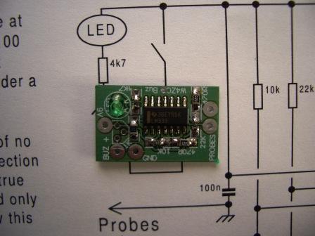
For PCB assembly, Beeper overlay drawing
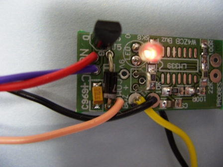
Please note! The two resistors shown on the PCB as 470R SHOULD BE 100R
Use this drawing for connecting up the PCB. (Old version without auto OFF switch)
Schematic and PCB foils to make your own here. Includes auto off. 2nd Oct 2009
November, 2009: A new version of the Beeper was included on the COMBO PICaSTAR panels.
This one has the auto off feature built in.
The schematics are here. The gremlins got in though, Cap. and Diode inserted as below is correct. This PCB is only part built. I used a 1uF Cap. and timeout is about 30 minutes.
Old version below without auto off.
CAUTION:- there is no reverse polarity protection in this design. Reversing the battery may cause destruction of the IC.
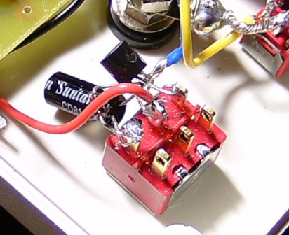
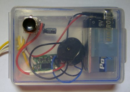
This is Chris's Beeper.
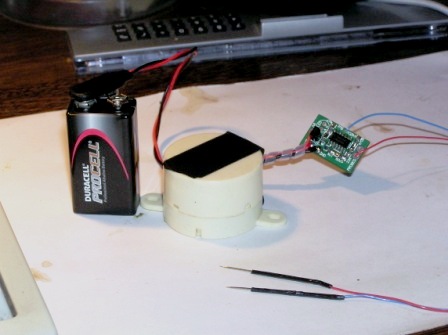
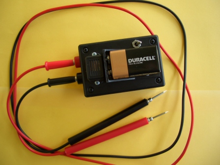
This is VK3PE Beeper. Going overboard I guess, but I had the jiffy box and multimeter leads in the "junk box" and this is the result. I put the battery on the outside so it is more easily accesible and not forgotten. The probes were sharpened to a point on a grinder.
Glenn & Chris
Hi Glenn,
I thought that you may be interested in the following circuit. It is a Sleep Automatic Turnoff Switch that can be used to replace the power ON switch on the low voltage W4ZCB continuity tester, or whatever. Push the button once and it turns ON, push the button again while it is ON and it turns OFF. Leave it ON and it will automatically turn OFF in about ¾ hour.
The extra cost will pay for itself as the cost to replace a flat battery will be more than the cost for the extra parts.
After making the Auto Turnoff Switch I realized that I could have used a spare terminal on the other half of the DPST switch for the Source, Cathode, Capacitor connection that I have floating in the air (the blue wire). A junk box micro-switch could have been used instead of the Jaycar DPDT switch. No the circuit isnt my design I had it on my hard drive but I cant remember where I got it from, after two flat batteries I decided to use it.
Parts used were: 1 x 2N7000 N Channel Enhancement TMOS FET Transistor Jaycar ZT2400
1 x DPDT Push button switch (only needs a SPDT) Jaycar SP0714
1 x 4.7uF Elect Capacitor Jaycar RE6058 1 x 1N4148 Diode Jaycar ZR1100
Roderick, VK3YC
12 Jan, 2009
Sept, 2009, NOTE:-
This auto off goes in series with the positive lead from the battery, to the beeper. The red dots are linked (2 links)
November, 2009: Auto off has been added to the PCB that is included in the Combo PICaSTAR panels.
November 16, 2009