DDS Filter
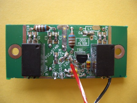
DDS Filter component placement
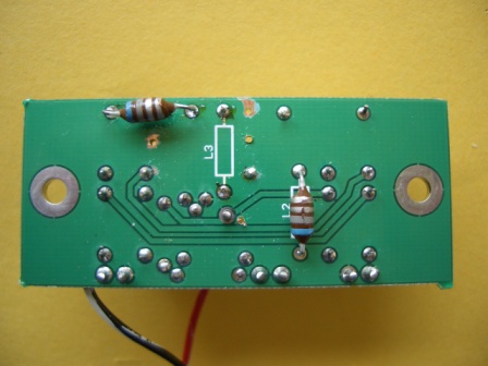
Please note the CORRECT fitting of the inductors is shown below. (Ignore the extra holes in PCB) The inductors should be spaced up a little from the PCB, not pressed hard down. I spaced mine about 2mm.
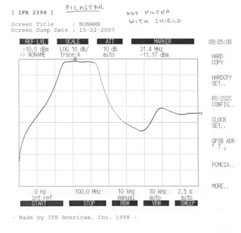
DDS filter built and tested. Performs as per Peter's description in part 14. Mine has ~1dB loss and the response above about 60MHz starts to rise due to some unwanted coupling across the filter. (See Yahoo message #24641 for more info) The width of the scan in the graphs is 100MHz. Top line is 0dB reference not 10dB as on the picture.
Measured response is ~36dB atten at 10.7MHz and filter passes approx. 24 - 44MHz.
For VK builders, I used the (cheaper) Jaycar relays which are the same pinout as the Farnell type originally specified. Either type can be fitted though.
November 13, 2007