PCB Hints
This page is just to give you some ideas for the use of these PCB's plus any other usefull ideas.
Last updated on January 13, 2009 (power switch mod. added)
TOOLS
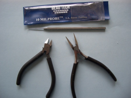
These are the tools I used to assemble the PCB's.
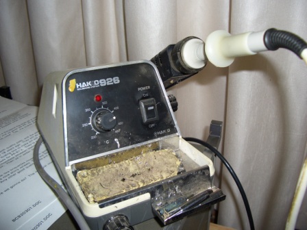
Standard side cutters and small pliers for bending component leads. (use larger pliers for other things though) Cutters are about 100mm long. Perfect for electronic work, with fine cutter section. Small temperature controlled iron. Tip size should be about 0.4mm or so. (OK, I need a new sponge also) The fine tipped probe (left) is very handy for moving IC leads, teasing out co-ax braid and a thousand other uses. Very similar to a Dentists tool. Also, not shown, is a pair of small tweezers. These are used to hold the SMD parts while soldering them.
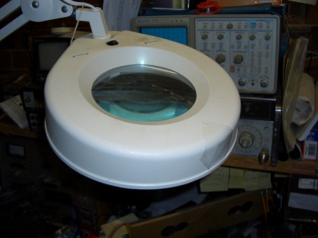
To see what I am doing, I use a magnifying lamp. These are quite common and have a round fleuro tube underneath. It is mounted on an articulated arm which can be clamped to the edge of a bench.
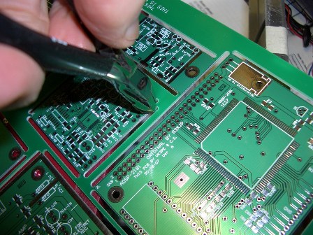
This is the method I use to remove the PCB's from the Panel. A sharp pair of small side cutters is used with the cutting face outwards, to snip the small segment of material left at the corners of each PCB. Simple to do.
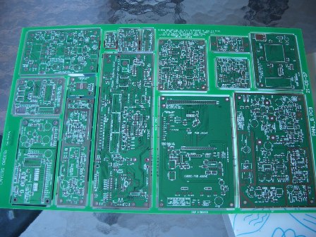
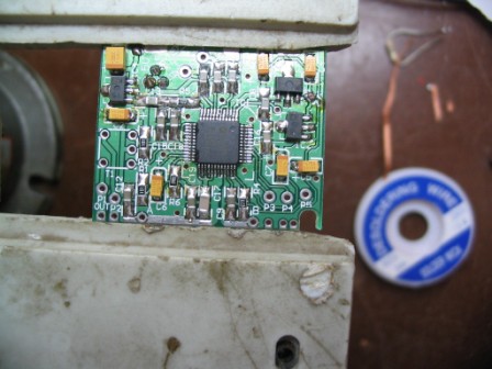
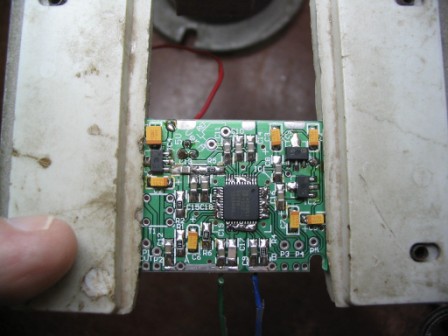
That's the CODEC board, with the DDS filter above it and the DSP board to the right.
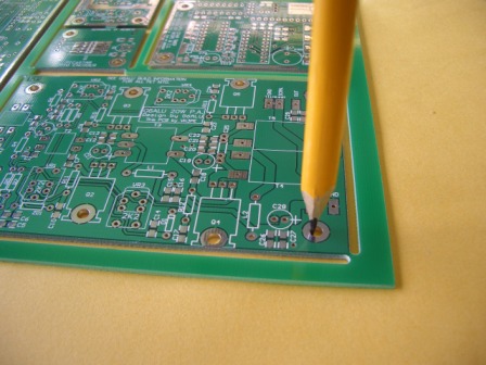
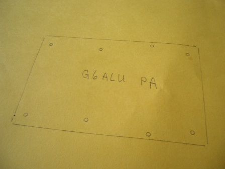
It's a good idea to make a template of each PCB before you place components, so you have a drill drawing for mounting.
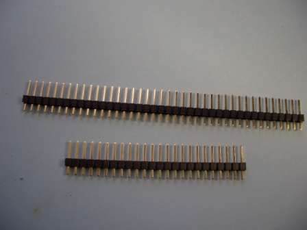
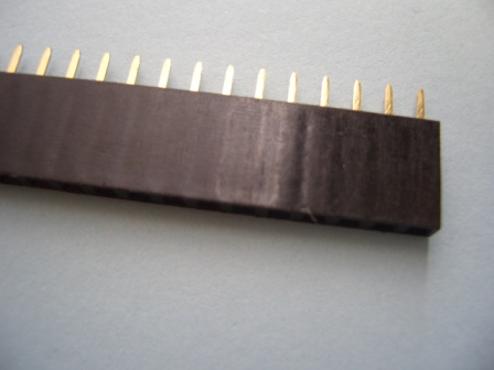
This is a sample of the Male headers (0.1" pitch) referred to in the BOM for these PCB's. These normally come in sections 40 pins long which can be snapped to length. The right hand picture shows a section of a mating type PCB socket. To use this part on a cable to mate with the header though, would require that the section where the wires are soldered on, be glued with Araldite or similar, as the pins will fall out. These sockets are of course normally inserted into a PCB. There are other sockets which are more suitable, having a housing with crimp terminals. There are also some locking types which may be useful in some areas.
Soldering these PCB's. I use the thinnest solder I can buy locally, which is 0.355mm diameter. It's fine for all but the DDS and CODEC chips. If you can find a finer solder, try to get some for those chips. You can use the 0.355 but have to be careful.
Soldering SMD chips:
Jan, 2008, From Viv, pictures of using the solder all pins then solder wick off the excess method of soldering the DDS chips. Works for CODEC also.
June, 2008
Jay has posted me some tips he uses for assembling SMD parts:-
Hope you don't mind if I pass along a couple of tips which YOU don't need as you are already built but might be useful for some of your beginning builders. 1. Soldering the AD9951 and Codec chips with no sweat.
You need a low heat iron...I use an Antex 18W with a 0.5mm tip and also thin solder...I use 0.015" = 0.35mm silver bearing. Once you have the little devil correctly positioned and a couple of corners nailed down...don't even think about trying to solder each pin separately unless you have eagle eyes and a rock steady hand. Just drag the iron tip and a LITTLE solder down 2 or 3 pins at a time...ignore any bridges...until one side is finished. Then take a cotton swab and dip it in liquid flux and run it along all 12 pins. Then run the iron down the pins again, even 2-3 at a time, and watch the solder jump from the bridges onto the pins faster than a cheapskate grabbing a free tinnie. I use a green liquid flux that is not even good for electronics...it's corrosive and conductive but you just wash it off under the tap when all 4 sides are done. (make sure NO water isleft, Glenn) No braid necessary. 2. How to get those smt parts straight without a microscope. I found that when I held the smts with tweezers for soldering, the things usually ended up crooked...also I couldn't hold tweezers and a magnifier in one hand. So, after you have tinned the first side, pick up the part with tweezers and plonk it down roughly in position. Then holding one of those little jewellers screwdrivers between thumb and first finger (LH for righties) and, if you need it, a folding magnifier in the pocket between those two...push the part into position using the flat blade of the screwdriver and soldering iron tip...then tack it down...works every time and things look very neat. I was able to use this method to fit 0805 caps instead of 0603s, which I didn't have, as the tuners in the BPF.
I hope the above may help someone down there. > Cheers. > > Jay
26th Nov, 2008
Hi Glenn,
While building my PicaStar BPF, I found that a local supplier had supplied 220pF 0603 capacitors in a bag that was marked 100pF.This prompted me to check the other capacitors that were purchased.
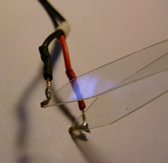
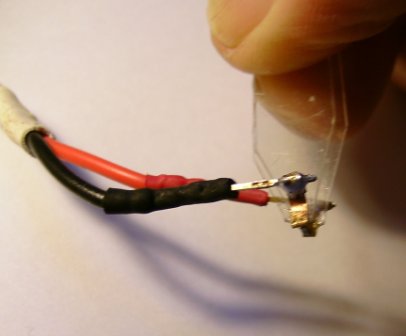
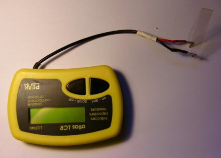
Problem was connecting the Peak LCR meter to the 0603 footprint capacitors. They were too small to use with the clips that were supplied with the Peak meter. I remembered that Peak sell a SMD test clip that looked like plastic tweezers with metal tips for connection to the SMD and LCR meter. I didnt have any plastic tweezers to make a test clip and I wanted to finish the BPF 80m section, the following is how I made my test clip.
The tweezers were made from a plastic strip cut from a soft plastic molded packing that my lap top power supply came in. The SMD connection contacts are bent brass strips with an old connector pin soldered to it. Pliers were used to squeeze the contacts to hold them on the tweezers and super glue was used on the top side. A file was used to clean the contacts to ensure a good electrical contact with the SMD component. Dont forget to make sure you calibrate the LCR meter with the new test clip connected. Glenn, you may want to add this to your website its up to you.
Regards, Roderick Wall, vk3yc.
Hi Glenn,
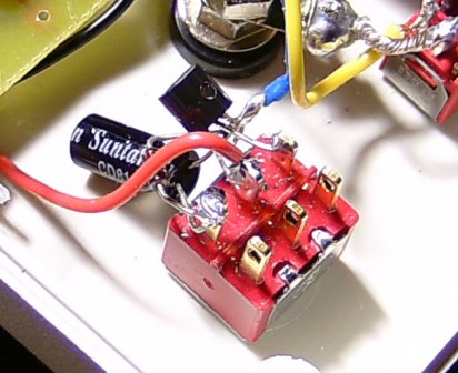
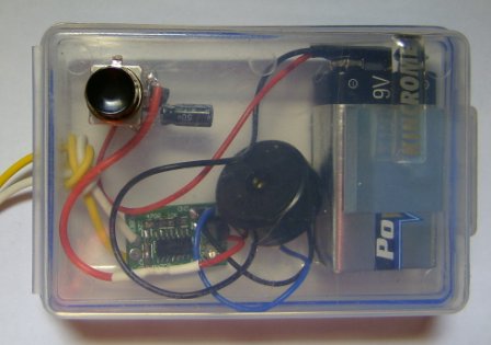
I thought that you may be interested in the following circuit. It is a Sleep Automatic Turnoff Switch that can be used to replace the power ON switch on the low voltage W4ZCB continuity tester, or whatever. Push the button once and it turns ON, push the button again while it is ON and it turns OFF. Leave it ON and it will automatically turn OFF in about ¾ hour.
The extra cost will pay for itself as the cost to replace a flat battery will be more than the cost for the extra parts.
After making the Auto Turnoff Switch I realized that I could have used a spare terminal on the other half of the DPST switch for the Source, Cathode, Capacitor connection that I have floating in the air (the blue wire). A junk box micro-switch could have been used instead of the Jaycar DPDT switch. No the circuit isnt my design I had it on my hard drive but I cant remember where I got it from, after two flat batteries I decided to use it.
Parts used were: 1 x 2N7000 N Channel Enhancement TMOS FET Transistor Jaycar ZT2400
1 x DPDT Push button switch (only needs a SPDT) Jaycar SP0714
1 x 4.7uF Elect Capacitor Jaycar RE6058 1 x 1N4148 Diode Jaycar ZR1100
Roderick, VK3YC
12 Jan, 2009
January 13, 2009
Glenn
Last updated on January 13, 2009