REWINDING TOKO™ STYLE COILS
This is general information on rewinding Toko coils. Success in using old cores from equipment, eg CB radios, depends to some extent on luck. In that you will have to find a suitable former. The ones with the large tuning slugs are usually not suitable, in my experience. Removal from old PCB's can be difficult also. I find that a solder sucker works quite well. Plus SoderWik™ and a flux pen.
TOKO coils used to be freely available new, but are no longer made. So use of second hand parts from various sources may be needed.
Update April 2024 Recently I have found that Aliexpress have these Toko copies available in lots of 10.
Search for "10 sets of FM adjustable inductive coupling coil intermediate frequency transformer skeleton DIY accessories" About US$5.
The listing picture should show enclosure width of 9.8mm, a bobbin, magnetic cup and CORE. I bought a set and they seem to be fine, with the same AL value from what I can see.
In order to rewind these cores, it is necessary to know how many turns you will need !
For the formers I used here, the formula is uH = (16 x turns^2 )/1000 (NOTE:-this may not be the same for your coils !)
Or, re-arranged: Turns = SQR Root((uH * 1000)/16)
The cores I used here have a white ringed top around the tuning slug when viewed from the top. The "16" is the AL value. Other coloured types seem to be the same AL value. You may need to wind on a reasonable number of turns onto an unknown former and measure the inductance. Rearrange the formula to calculate the "AL" value. Some types (rare) have an AL value of ~8.
Once you establish the AL value to use, calculate the number of turns for the inductance of all the coils you need. For a PIC-a-STAR BPF, there are 3 identical coils per band. Plus the IF trap. For 10.7MHz, the inductance needed is about 3.3uH.
Wind a test coil for the lowest and the highest value of inductance you will need. Measure the values of inductance and see if they test OK. ie you can adjust the inductance to the value required. You will also need appropriate sized wire. A thicker wire can be used with fewer turns of course. For the high values of inductance, with many turns, a thinner wire will be needed, in order to fit on the former. For measuring Inductance, I use an AADE meter which you can find on the Web. It is available as a kit or fully built. UPDATE: Sadly, the AADE meter is no longer available due the designer, Neil Hecht, passing away on Aug 19th, 2015.. I think there maybe similar inductance meters available that can measure down in to the sub 100 nH range.
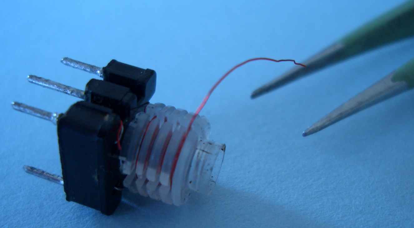
Removal from the can: I use a pair of wide nose pliers that can grip the 2 pins, hold the can with fingers, then pull out the internals.
Use a pair of tweezers or a sewing needle and find the end of the wire, break it free, then unwind the turns completely.
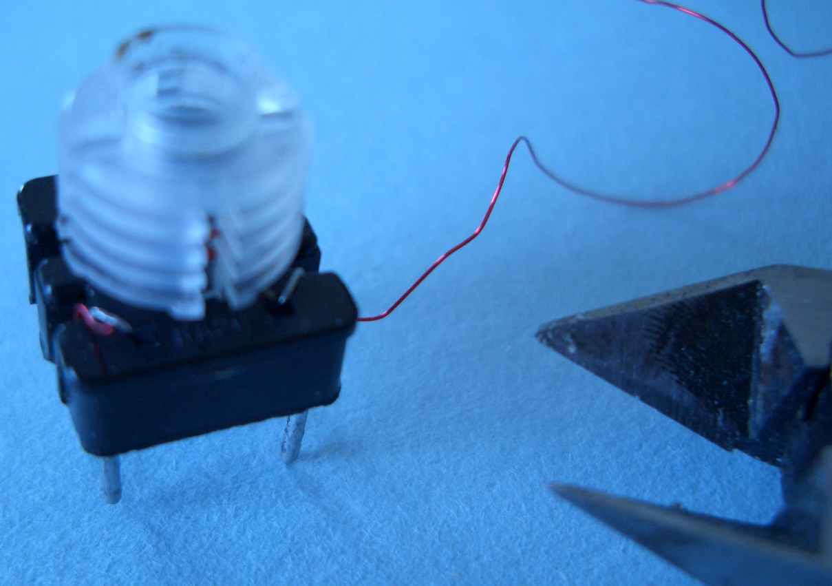
Snip off the capacitor leads shown here.
Remove the existing capacitor. Don't break the side of the former as I did here !
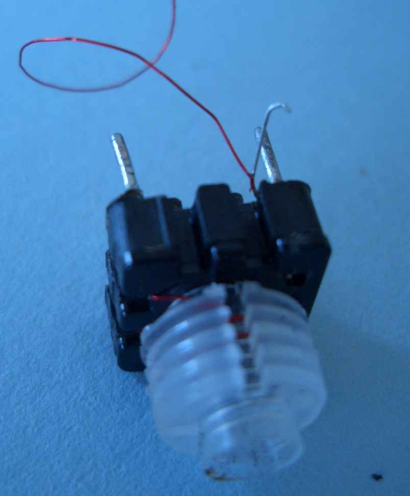
Grip the capacitor and copper wires with a pair of tweezers, heat the pin with a soldering iron and quickly slide the wire off the pin. Clean the pin with solder wick if needed. Be careful not to apply too much heat or the former will MELT !
Repeat for all the wires. Now you are ready to rewind the coil:-
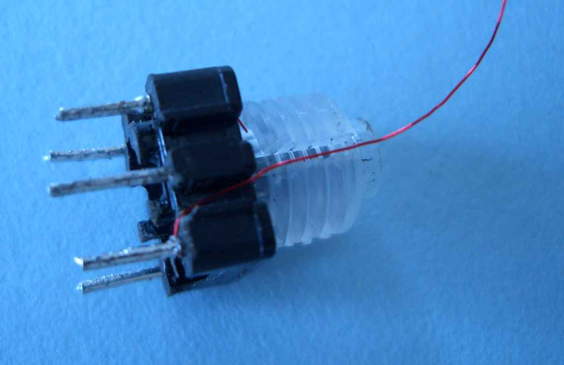
When rewinding, tin the end of the wire first, for about 8mm and wind 2 turns onto the pin. Lightly solder it on and then run the wire in the direction shown.
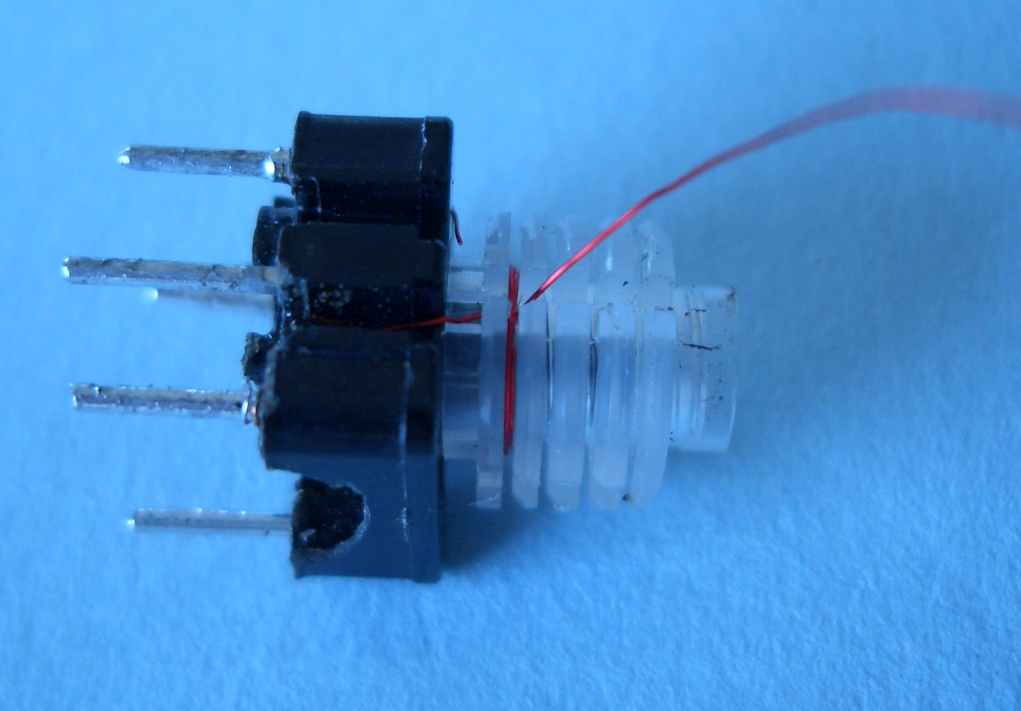
Start winding into the 1st section. The number of turns calculated is divided by FOUR and that number of turns is wound into each section of the former. If you have an odd number of turns to wind, make the last section, the lower number of turns. As each section is wound, carefully move the wire into the next section as shown.
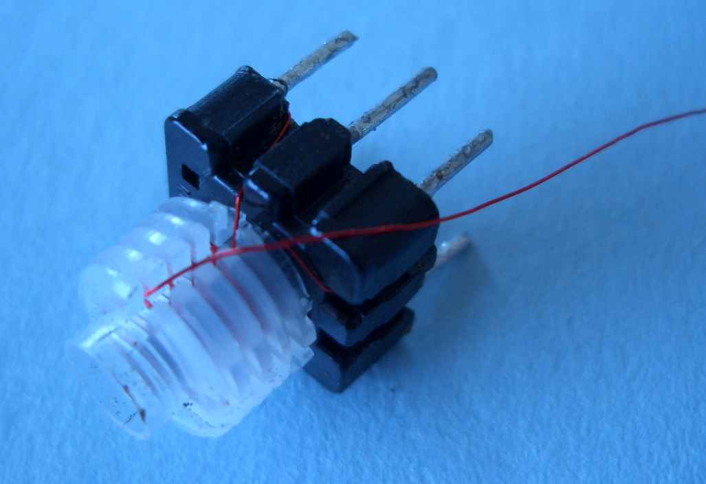
When the last of the turns has been laid, bring the wire back as shown for termination on the pin. Tin the wire when it is in the position above, then wrap it around the pin two times. Solder and trim excess. The wire should run inside the groove on the former of course or it will foul when the shield is refitted.
Fit the shield assembly back over the former and make sure it is pushed right in. Then, you can measure the inductance and adjust as required.
Last updated on:- January 1, 2008
Page created by VK3PE on Feb 23rd, 2008