 The
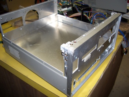
left-hand picture is the instrument I started with and then you can see it stripped
out totally, with the home-made "U" shaped chassis installed. The
front panel is the old one and I will make a new one for it also. See below.
The
left-hand picture is the instrument I started with and then you can see it stripped
out totally, with the home-made "U" shaped chassis installed. The
front panel is the old one and I will make a new one for it also. See below.VK3PE build of STAR PCB's
Unofficial site !
Last updated on October 3, 2008
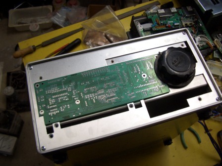
This is NOT a "how to build a PICaSTAR". It is simply an undated Blog of how I am building my STAR using my PCB's contained on the panel detailed on the pages here.
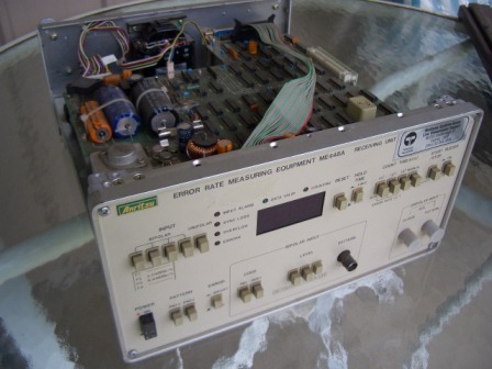
My initial thoughts were what to use for a case as I don't have any large amounts of PCB stock suitable for a PCB case but do have an old instrument I bought at a sale some time ago for $10.
This is a commercial case and looks quite nice in original form as it uses some nice castings for the front panel perimeter. I stripped everything out of this case except the chassis, but decided it would be too hard to rework, being 2mm steel. So I pulled that out also and bent up a simple "U" shaped piece of 1.6mm aluminium sheet.In the end, the only thing left of the instrument, was the front panel surround and the top and bottom covers ! I happened to have some thin sheet fasteners bought at a rally so used them in the chassis.
The
left-hand picture is the instrument I started with and then you can see it stripped
out totally, with the home-made "U" shaped chassis installed. The
front panel is the old one and I will make a new one for it also. See below.
This case is 280mm wide x 140mm high & 290mm deep.
Perhaps a little on the high side.
 Now
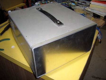
you can see the new front aluminium sheet panel and the original covers fitted.
A fairly nice case for my STAR with minimal expense.
Now
you can see the new front aluminium sheet panel and the original covers fitted.
A fairly nice case for my STAR with minimal expense.
A new rear panel was also made. See below.
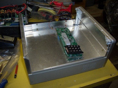
 This
is a 'dummy" view of the PICnMIX PCB in place to see how the knob will
fit. Of course, the PCB will be mounted behind the panel ! That's the old panel
that came with the case. It was removed.
This
is a 'dummy" view of the PICnMIX PCB in place to see how the knob will
fit. Of course, the PCB will be mounted behind the panel ! That's the old panel
that came with the case. It was removed.
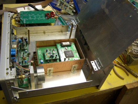
There is about 30mm under my chassis for PCB's and wiring plus it also enables a front microphone socket to be fitted easily plus Morse key & headphone sockets.
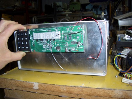
 I
was torn between red or green displays.
I
was torn between red or green displays.
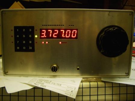
Red displays finally used.
Four pin mic socket and socket for Morse key added also. A piece of red perspex fits in the hole over the displays.
30th March, 2008. My STAR made it's 1st QSO on 80M, with 18W into an inverted V. Feels good !
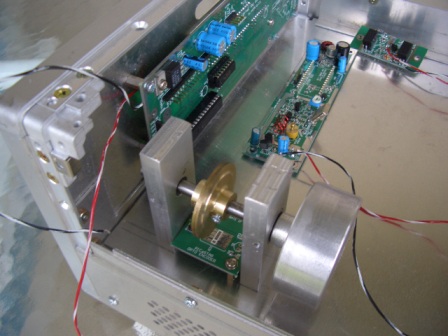
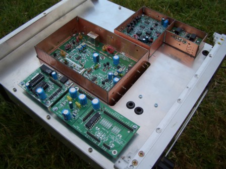
STAR was operated with no BPF's and a temporary arrangement of relays for MR and PA T/R switching. A hinged deck panel was added also to take the LPF pcb. In this case, a temporary CDG2000 LPF with 160 & 80M filters only. No switching so 80M wired in directly. When the new LPF panel arrives, this will be replaced of course. A shielded box will be fitted around the LPF also.
The BPF will be located at the far end and will be mounted under this panel. Eventually, a 150W G6ALU PA will be fitted along the back panel, with the G6ALU 20W PA and the whole PA area will also be shielded.
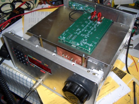
Above: temporary LPF filter fitted for 1st QSO on hinged deck. This is the configuration used for my first STAR QSO.
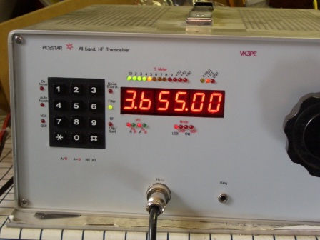
August, 2008, my Star is now on-air with 140W PA and LPF.
My front panel was printed on a light grey Polyester material with an adhesive backing using a colour Laser printer.
3.655MHz is the STAR net in VK3 on Monday nights at 8pm local time.
Last updated on October 3, 2008
Originated September 30, 2007