| uSDX Sandwich |
The uSDX is a very clever HF rig that uses an Atmega328P (ie same as a NANO) to essentially make a rig using DSP techniques. The original code is by Guido, PE1NNZ. See pe1nnz.nl.eu.org The output stage uses a low cost FET in class E to produce about 4W pep. |
There are a number of variations of the original hardware (ie PCB) designs available. ....................... One is based on the QRP Labs QSX, modified to become a single board (plus LPF's) HF rig. Other dedicated PCB versions are also available. eg by WB2CBA and DL2MAN. Refer to Groups.io "uSDX" group for further details. I elected to go with the 'sandwich' design by DL2MAN. The sandwich is so called because it uses 3 PCB's slightly larger than a credit card, stacked one on the other, to form a complete HF rig. All use the same software, as far as I am aware. Refer to Github June 11th 2021: After chasing some parts, I now have the uSDX receiving with great sensitivity, similar to my IC-705. And also transmitting, I am getting just over 4Watts out with 85% efficiency. So far only on 80M as I am lacking some parts for the other filters. |
|
| Battery board |
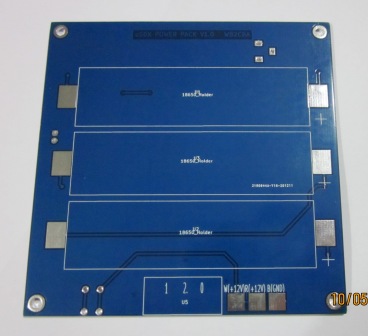
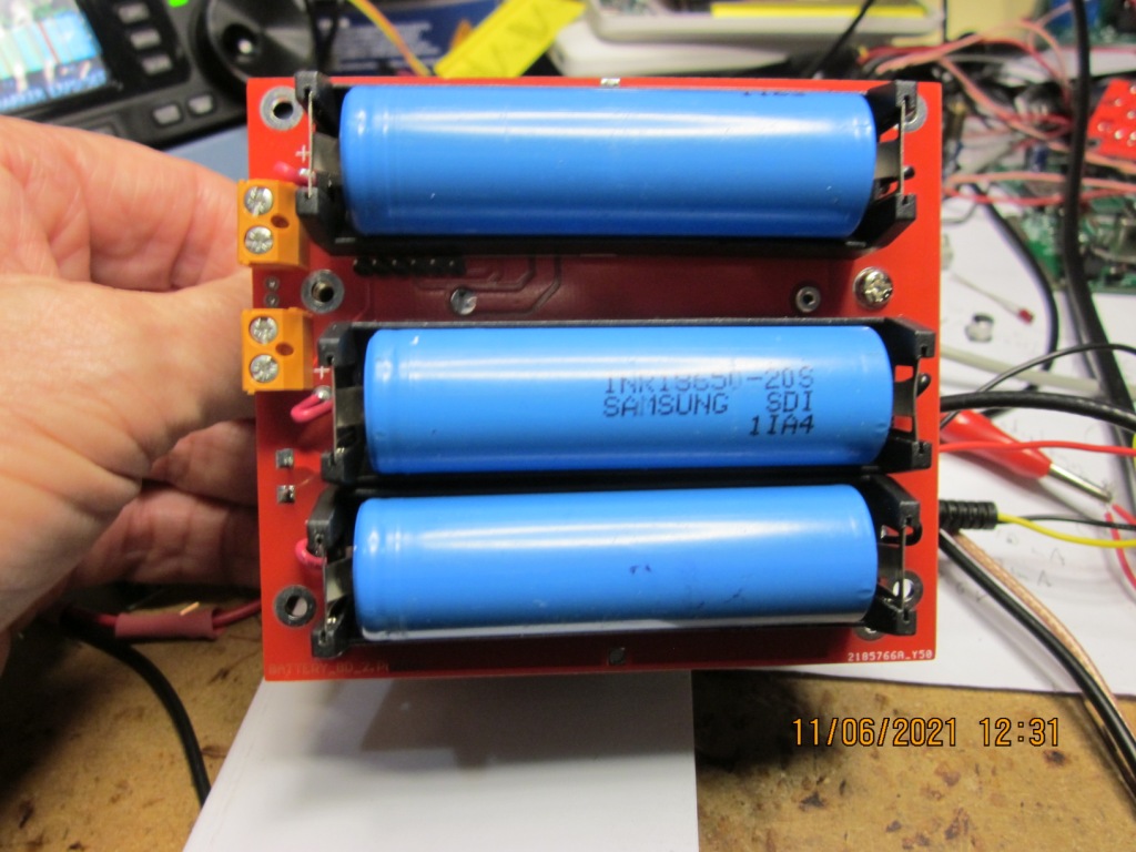
WB2CBA? designed a 'battery board' which holds 3 x 18650 cells to be come the power supply for the rig on his PCB version. With the uSDX, it then becomes a self contained Rig ideal for portable operation. This is the original battery board: (top and bottom) About 98 x 98mm.
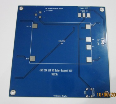
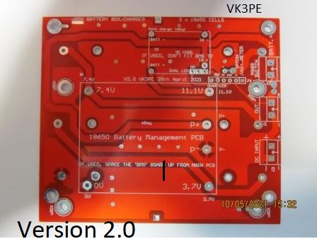
I built one of these boards (above) up with new 18650 cells and the recommended 'battery management' board which is sourced from eBay™. Unfortunately, I didn't have much luck with this design. Not the fault of the designer but appears to be a poor quality eBay sourced balancer module (BMS) which is fitted to this board. After charging up the 3 cells using the board it promptly destroyed one cell. Thinking I simply had a bad cell, I fitted another new one. And this one also was destroyed. Both in the central section of the 3 cells. My conclusion being the BMS module has some sort of fault. Not wanting to pursue this, I decided it was better if balancing was done by other means and a simple charger only PCB be fitted to the battery board instead. This is a picture of my new blank PCB which has been designed to fit onto the rear of the DL2MAN sandwich. Note it is overall, a bit larger than the sandwich due of course to the actual size of the 18650 cells. I left the original BMS facility which is the larger rectangle on the PCB. But added the smaller rectangular pcb, being the new charger only board also from eBay. Only one of the boards should be fitted. The charger board I used has a bi-colour LED to indicate charge and charged (I think) PCB is about 99 x 85mm. It's a little different in that it uses through hole wired in battery holders, not the SMD version of the original. smd 18650 holders are not easily found in VK, and the cells themselves cost more in smd. The 18650 cells are mounted on the rear. This PCB features an eBay Charger module which is the small rectangular area near the top of the PCB. (Parts not fitted of course as shown here) I had problems with the original eBay "equaliser PCB" that was specified (the larger rectangular area) that I tried originally. It seemed to be faulty and damaged a cell when charging. So now I am going to use this new part which just charges the 3 cells. It has provision for a dual LED to give "Charge" and "Charged" status. This LED will be on the front panel when the whole peoject is put into a case. In case of catastrophic failure, I have added two 'fusible link" tracks on the PCB which should blow if a high current fault ever occurs.
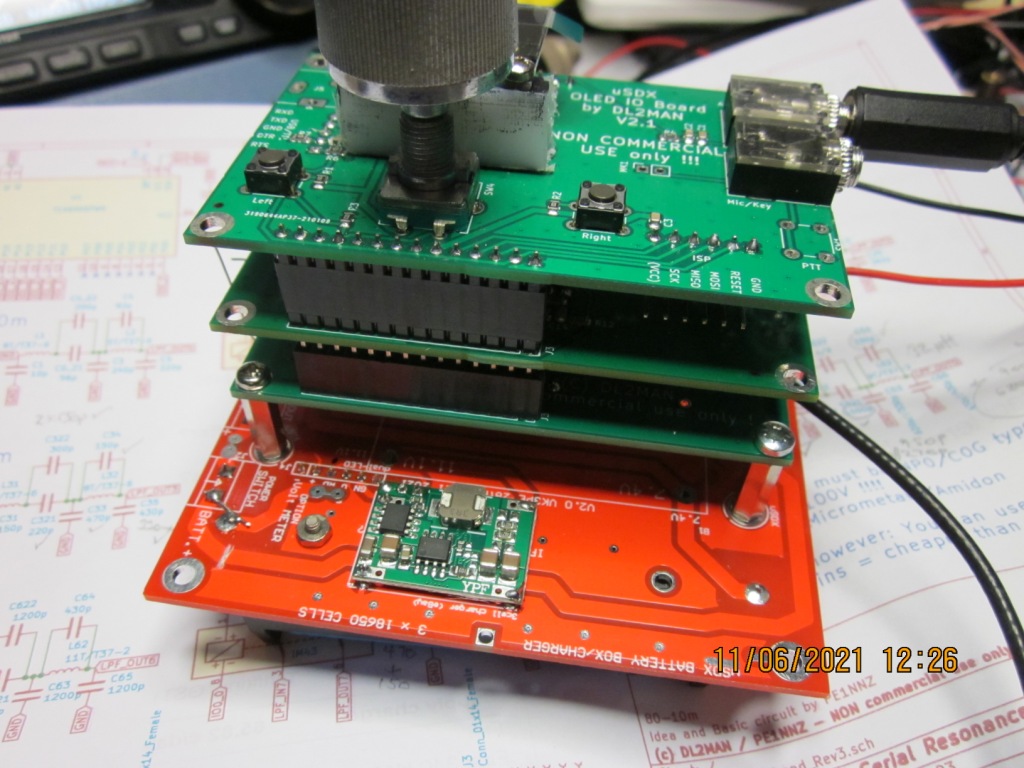
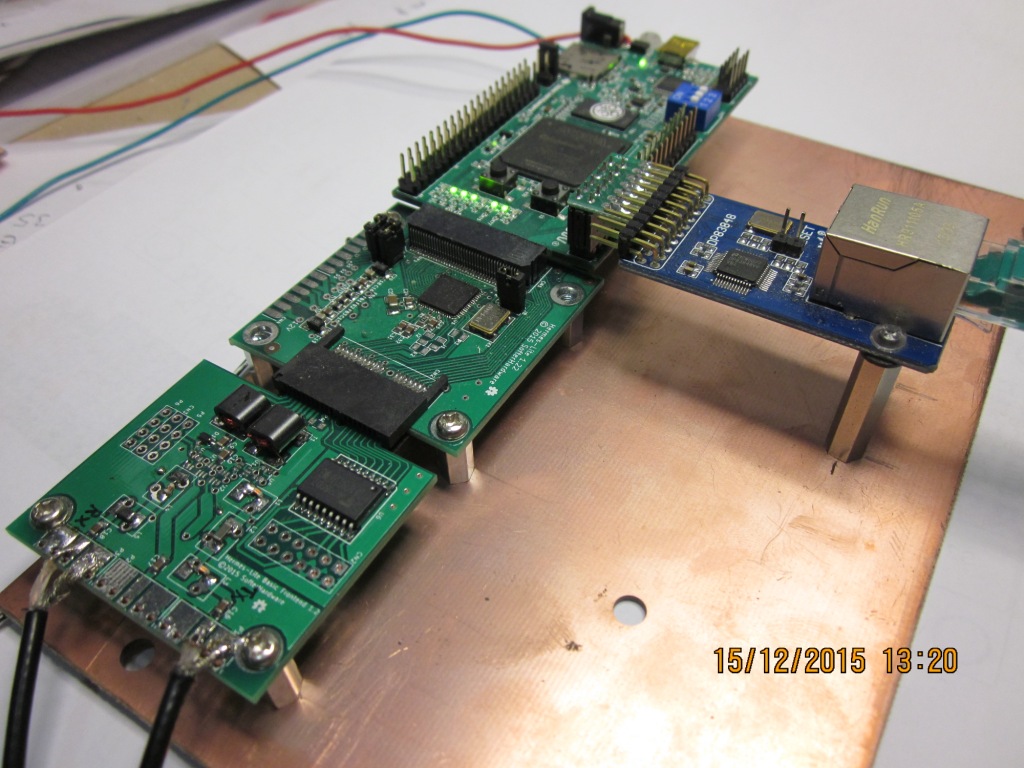
Update: June 11th 2021: This V2 pcb above has now been built and tested with the eBay charger board fitted. (pictured below) A small problem was found during testing but a track cut fixed that. It was to do with selecting either the new charger module or the original BMS board. A later update might be done for that. Please note, the battery board is larger than the uSDX board. Unavoidable due to the size of the 18650 cells. As it sits below, it weighs 335grams with cells fitted. (ie no case)
Nov 24th 2021:- There's been some discussion on the UCX group around tailoring the response of the Electret Microphone and adding some gain. Currently talk is using the MAX4466 (mic amp) device coupled to a MAX7426 (LPF). I have designed a small PCB for this and it is currently out being made. All smd. I hope to have it and both MAX devices next week, to test it out, initially as a PCB only and later connected to the uSDX. I am also building a V1.02 version of Barbs design for the uSDX.
More to come.......
This web page was designed by VK3PE (see QRZ.COM) and are my own experiments and build. No guarantees are given or implied, that this will work for you. Created on May 10th, 2021 and last updated on November 24, 2021 |