home
K3NG ATU by VK3PE |
|
Glenn's Hobby Pages | ||||
| VK3PE | |||||
| home |
|||||
|
|||||
The K3NG ATU (Automatic Antenna Tuning Unit)
*Under construction, come back soon.*
NEW Sept 2022:- A really nice build by Luca, IK2LRN
see also the QRP ATU-10 by N7DDC, which uses latching relays. NEW link, 11th May 2022
NEW 9th May 2022: A fully balanced K3NG ATU version by Simon, G0FCU
Dec 28th, 2020 OLED sketch added and QRP SWR pcb Gerber's.
January 5, 2019:-Added SOURCE OF 3Kv SMD CAPACITORS smd capacitors of mainly 3kV rating were used in the ATU. The link shows possible sources and values to use.
build info the VSWR board December 17, 2018
New Ideas for the 100W version! 26th Aug 2017
Smaller Control board with 0.96" OLED display (or various other I2C displays) plus smaller QRP SWR pickup Feb 2018
Old update (information on the V1.1 control PCB and also the smaller 'OLED' PCB.)
BACKGROUND:
K3NG is well known in Amateur Radio circles for his projects, using the Arduino platform to develop a number of very useful Amateur radio projects.
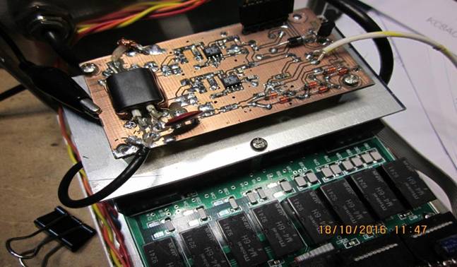
One of them, which interested me, was the ATU. K3NG has a web page for the project although it is a little limited in content, as he never progressed past his working prototype, built 'ugly' style. (Pictures below) It's fairly unique though, in being a balanced tuner, able to feed for example, a doublet antenna, fed with open wire line. It can also be configured for unbalanced output.
I (VK3PE) have long wanted to build such an ATU but being limited in my Arduino programming knowledge, decided I would tackle this project as a good starting point. I wasn't that keen on duplicating it K3NG ugly style but preferred to build with PCB's. The ATU uses a standard configuration of variable L & C values in the usual binary fashion with the Inductors duplicated to form the other arm of the balanced format. The work shown here, is NOT for a balanced type.
This page then, is how I built the K3NG tuner and also a 'QRP' version. I made use of some low cost eBay PCB vendors to make the PCB's for the project.
The K3NG design uses standard relay types. If very low power operation is an aim, as in Portable use, then latching relays would be the way to go. I stuck with the standard relay types though, as latching relays would require some major changes to both the Arduino Sketch and also the Schematics and thus, the PCB’s themselves. Since I do not operate Portable, it’s not a problem for me. The other major factor is cost. Latching relays are much more difficult to obtain due to availability in VK at least and cost is much higher, generally.
NOTE: As of time of writing this, Bill, K9ZC, is developing an ATU using latching relays. It’s not based on the K3NG design. Refer to discussion here https://groups.io/g/QRPLabs/topic/qsx_radio_feature_requests/24919594?p=,,,50,0,0,0::recentpostdate%2Fsticky,,,50,2,0,24919594
NOTE: There is also another ATU designed for home construction. It is by Peter Rhodes, G3XJP, and a number of these “PIC-A-TUNE” ATU’s have been built apparently. Peter has now removed all build information from the WWW (along with his other projects) so this is not a path to pursue.
K3NG’s original design utilised ‘ugly’ construction (see picture at end of this page) and he never designed a PCB for the project. I was not keen to go down that path, so designed some PCB’s for the project. I split the design into
Since I had different uses in mind for the project, I further split the design into ‘QRO” and “QRP” versions. The QRP version is not covered by K3NG. In this case my ‘QRP’ version should be ok for up to about 20-30W. Very low power though is limited by the sensitivity of the detector used. Traditional diode types may not work.
The design of the PCB’s also was dictated by cost. Currently, a 100x100mm PCB is about the sweet spot for cost, from the many on-line PCB makers (usually Chinese) So, to take advantage of that, the QRO version had to be made using 2 100mm sq. boards as you will see. The QRP uses a single board.
The “DRAFT” CONTROL BOARD
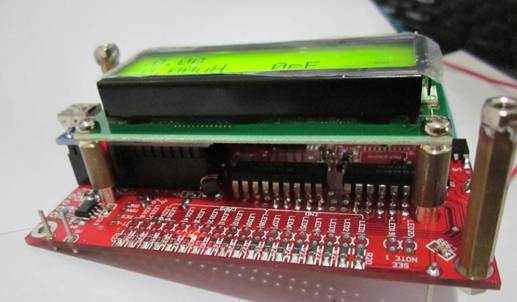
Initially, I had a PCB made that could contain a standard 2x16 character parallel driven LCD module, not the serial type that K3NG used. While it works fine, it required some Sketch changes and hardware also, so is not a path to recommend.
However, I will show you what I did, for interest sake. I actually made a couple of versions of this PCB due to inevitable ‘bugs’.
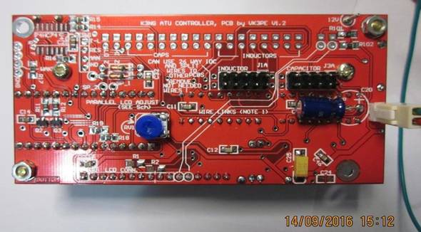
Pictures further below of the red PCB are the 'prototype' boards made. They contain the NANO board, relay drivers, power supply etc. (see schematic link below for details)
NEW May 5th, 2018: Version "1.1" PCB information (green PCB) Similar to the red V1.2 board below. Information for interest ONLY.
Schematic
Overlay showing parts values
Bill of Material pdf (BOM) Xcel format NOTE "Rx" is an axial resistor for LCD backlighting. It's shown as SMD which is incorrect.
Interconnections
Arduino Sketch. Refer to K3NG web page. This sketch was originally for a standard RGB type LCD module. For use with other display types, some Sketch changes are required and are not detailed by VK3PE. My C++ programming skills are very low!
The display used here was a standard 2 x16 LCD module with an I2C adapter PCB fitted on the back. Adapter came from eBay. Using the parallel type LC modules requires changes to the original K3NG Sketch. I do not have this information available.
An LCD with an MCP23008 chip adaptor board fitted was used in this draft board as I had one in stock. I recommend though, using the same RGB type that K3NG used. His software changes the RGB back light colours to indicate various states during tuning.
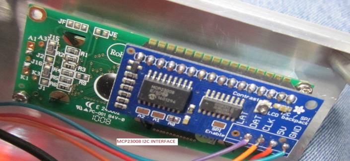
Adapter uses an MCP23008 chip. Recommended though is the RGB LCD typo used by K3NG.
Control PCB Schematic, BOM << Schematic updated May 19th, 2017 (missing ground on ULN2803 chips) NOTE:- MCP23008 are 18pin SOIC smd.
Control board, parts loading showing values.
SWR PCB Schematic & Overlay [no details or PCB available yet] Use K3NG's drawings.
Interconnection details [per K3NG's original]
Arduino Sketch (source code) Use K3NG's original sketch. I also fiddled with having an analogue meter on the panel. I used an MCP4527 serial (I2C) driven DAC to drive an analogue meter. Right now I have no sketch change details for this.
THE FINAL CONTROL BOARD (Feb. 2018)
I decided to make the Control board much smaller, Why, just because I could and it suits the idea of a smaller QRP ATU better. It’s much more tightly packed of course, and does require some smd skills to assemble. Schematic is identical to the K3NG one but has no provision for a parallel driven LCD module. K3NG shows such a scheme in his Schematic but I doubt he ever actually made one like that. ie with parallel LCD.
It’s possible though to fit other display types to the K3NG since it uses I2C serial for the display. See information further down this page.
NOTE ! To use an OLED display, some changes to K3NG's Arduino sketch will be required , SEE BELOW
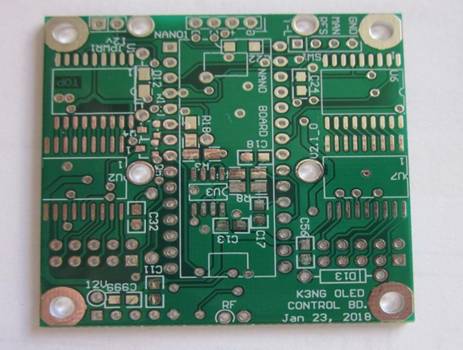
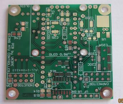 This is the 50x50mm Control Board, showing front and rear sides of the new smaller (50x50mm) Control board. It uses the serial (I2C) display and has provision to fit a 128x64 pixel OLED type directly to the PCB if required. See NOTE above though re sketch changes. Other types and sizes of serial (I2C) display other than that used by K3NG, can be used also if changes are made to the Arduino Sketch. See below. NOTE: THE LABLES ON THE CONNECTORS 'J3A' AND 'J1' ARE NOT CORRECT ! THEIR FUNCTION IS REVERSED, PLEASE CHECK CAREFULLY AGAINST THE SCHEMATIC !
The above PCB is virtually all SMD (surface mount parts) and they are fairly tightly packed and fitted to both sides.. Interconnections from the Control board to the L&C board are made by two ribbon cables. While I have had no issues so far, it might be prudent to fit a ferrite sleeve on these cables before crimping the connectors on.
NEW May 5th, 2018:
Schematic (pdf) of the 50x50mm 'Control' PCB
Overlay showing parts values (pdf)
Bill of Material pdf (BOM) Xcel format
Interconnections (pdf)
Arduino Sketch. Refer to K3NG web page. The K3NG sketch is for a standard RGB type LCD module using an I2C serial interface. Since my Control Board is the same schematic as K3NG, then it works as is. For use with an OLED (I2C) display, some changes are required.
My "modified" sketch. is here [Right click to save sketch] (Dec 2020) This sketch has some options to allow use of AD8307 SWR bridge and some different display types, including OLED. The Arduino NANO sketch is provided "as - is" and it is presumed the builder has some knowledge of Arduino programming. I can offer no additional assistance at this time.
SMALLER QRP SWR BOARD (shown for interest, NOT available now (run out)) -->>> See link below for Gerber files
While not quite finished assembly, here is the smaller 50x50mm SWR board for possible QRP use. (I don't have spare Boards)
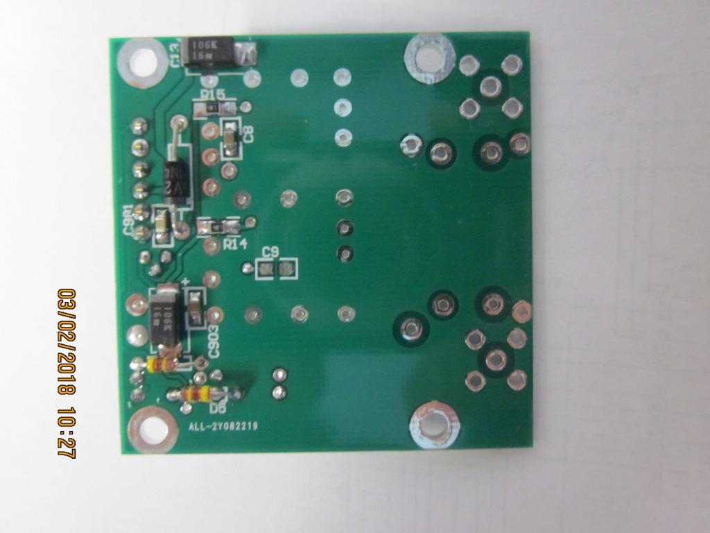
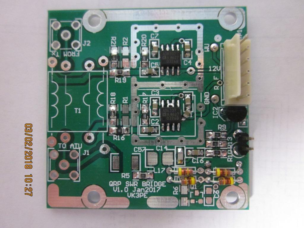
Above is a prototype SWR head using AD8307 Log detectors. NOTE: the K3NG Sketch needs to be modified to use these detectors as the detected output is in Log form, not ‘linear’ as from a diode type.. See link above for Sketch.......
Schematic (pdf)
Bill of Material (BOM) pdf file and Xcel file
Overlay by Component Ref number and by actual value (pdf's)
Integration drawing (pdf)
Everything above Dec 2020 (zip file) INCLUDES Gerber Files provided on an "as-is" basis. ie provided with no offer of assistance implied. You must be an experienced builder and can fault find if required. !.
--------------------------------------------------
THE L&C switching BOARDS
Even though the project is not finished, my busy mind thought that a QRP version might be a handy thing to build also for my WSPR station or MAYBE MY NEWLY ACQUIRED ICOM IC-705 RIG.. But only unbalanced. As it happened, I found a "special" on eBay for a 100x100mm PCB supplier. This spurred me to the QRP version which was duly drawn up, Gerber's made (email me) and sent out to the PCB vendor. IT'S VERY IMPORTANT THAT A METAL CASE IS USED OR AT LEAST A METAL BASE, AS THIS BOARD RELIES ON A GOOD GROUND THROUGH THE MOUNTING HOLES.
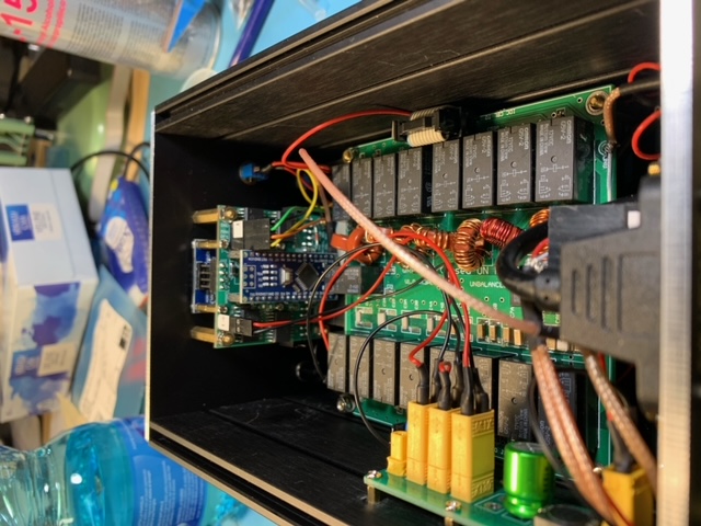
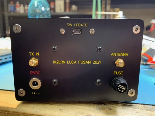
Luca, IK2LRN has built a version of my QRP ATU PCB (above) by K3NG and recently sent some picture of his excellent work.
------------------------------------------------------------------------------------------------------------------------------------------------------
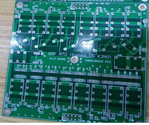
'QRP' L & C BOARD Vers 1.0 VK3PE
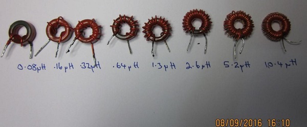
INDUCTORS FOR QRP VERSION, T50-2 CORES. (probably, it would be better to wind the 0.08uH and maybe the 0.16uH as air wound coils.)
The previously mentioned Control and SWR boards are unchanged from the 100W version and used in the QRP version also.
This time though I found a nice aluminium case 105 x 125 x 75mm in size which looked perfect to house the project. Of course, being QRP some components can be much smaller, eg relays and Toroids are sized accordingly and my gut feel is that it should be good for about 20-30W. (The full K3NG version is rated around 100W) Like all ATU's though, tune up should initially done at lower power settings from the Tx. eg 5W.
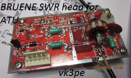 SWR head for the higher power version only. (see below)
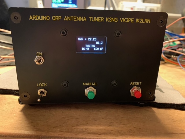
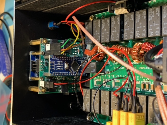
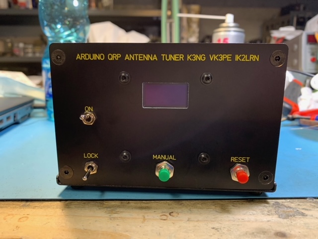
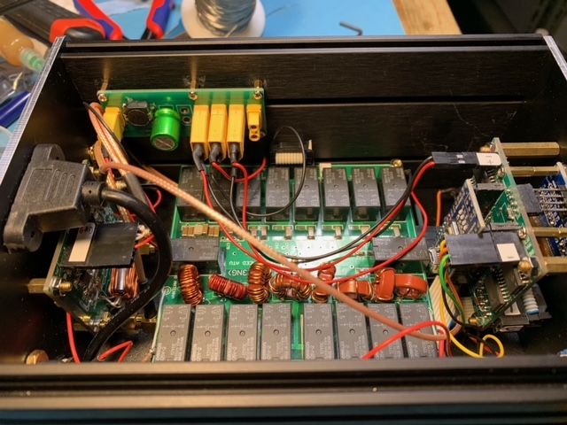
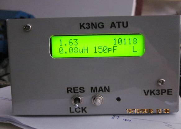
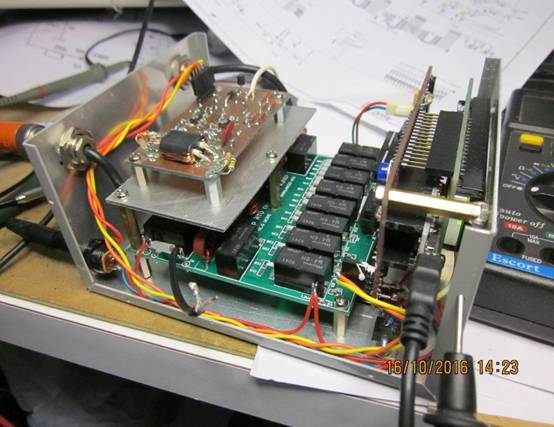
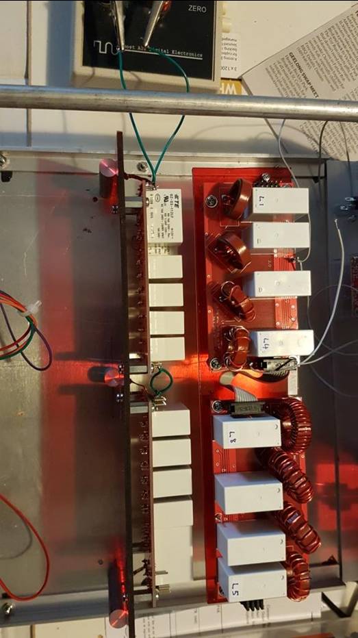
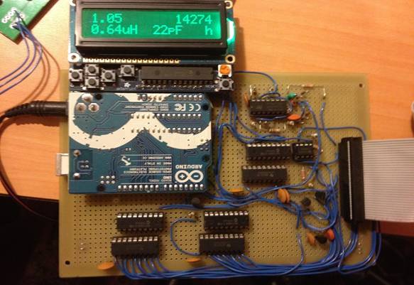
Below, is the QRP version now completed. In testing I found that the Bruene SWR head was not sensitive enough for QRP work so I made a PCB at home using the Stockton Bridge, on a BALUN core, with the outputs fed into two AD8307 Log Amp/detector chips. This works very well and I can tune with about 200mW of RF power now. It did entail some changes to the Arduino Sketch, as the calculations are different. Fairly minor though but they are NOT included in the K3NG original Arduino sketch. But are included in the link above. The front panel uses an LCD module per original K3NG although in this QRP version, the display is in 4 bit parallel mode rather than using an I2C adapter board. To the right, you can see most of the internals with the SWR bridge and AD8307's on the DIY board to the left, the main L&C board at the bottom of the case and the Arduino control board behind the front panel. If you look carefully, you can see the Arduino NANO board. {the picture is shown during testing, and a 50R load is connected on the output of the SWR board. } The switches on the front panel are Reset, Lock and Manual.
The display shows current SWR, frequency in KHz on top line, L & C values used and Hi or Lo Z antenna on bottom line.
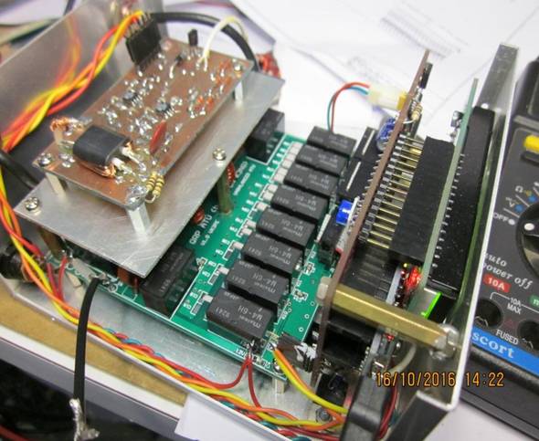
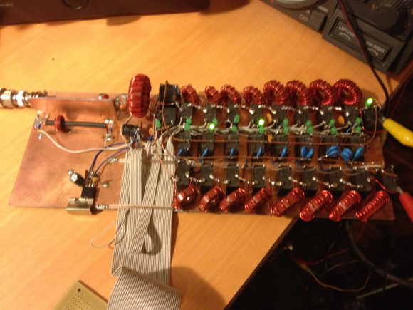
The pictures shows a home made SWR board utilising the AD8307 Log detectors.
As above, the QRP version uses a 100x100mm PCB on which are the required 8 inductors (in a binary sequence from 0.08uH to 10.4uH) giving a total of about 22uH. The capacitors run from 12pF to 1200pF each, also in a binary sequence as is usual for an ATU, controlled by a Micro. Each Inductor and capacitor needs to be switched in or out, using a relay for each. In addition extra relays are required to connect the capacitor bank to either the input or output side of the Inductors. The input and output correspond of course to the Transmitter input and the antenna port. The tuner takes the form of the usual "L" type match. The balanced version described above uses an extra set of identical Inductors, to make the ATU balanced. [I am yet to build a balanced version]
The relays used in the QRP version can be smaller, due to the lower currents and voltages encountered with low power. A common size of relay used known as a DIP relay. There are many brands available for these but the prototype here uses cheap relays from eBay known as "HK-19F-DC" 12volt relays are used in the QRP version of the ATU. {not in the pictures though}
For the capacitors in both versions, I used SMD parts of 3kV rating, available from Farnell/Element14™, RS-Components™ and no doubt, other suppliers like Mouser™ or Digikey™.
The control PCB is identical to the higher power version though, with no Sketch changes required, so a full display and even analogue meter could be used with a DAC. For the case used (above) space is very limited so no analogue 'SWR' meter was fitted.
Below is only for the "QRP" version built by VK3PE:-
Schematic QRP "RF" board
"RF" Board overlay (see PCB itself)
Interconnection diagram (coming soon)
Control PCB (see links above)
SWR PCB (not yet available, I used AD8307's in my SWR head)
Arduino Sketch:-
for parallel driven LCD module and AD8307 SWR head.
for ?
<<< above links coming soon >>
The “QRO” Version:-
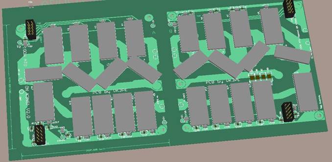
August 2017: I have had a re-think about the L&C PCB's for the 'QRO' (~100W) version. I decided to make two 100mm square PCB's to carry all the RF components. (un-balanced version only) They will be linked together with a couple of connection points and 2 ribbon cables (10Way) will then connect to the Control PCB. The Control PCB is identical to the QP version as detailed above.
Schematics and BOM link soon. Obviously, these mimic the K3NG web pages with minor differences.
 Connections are made via IDC cables. They should be carefully routed away from the PCB and high RF level areas.
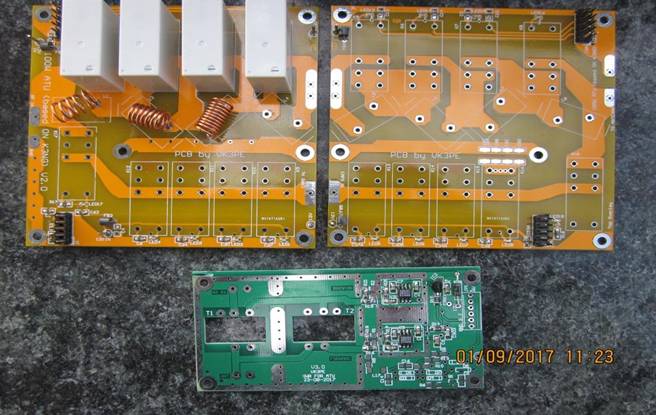
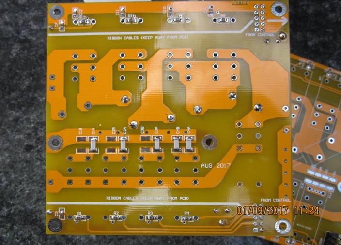
Here are the actual Proto version PCB's. The yellow boards are the L&C boards using relay switching. Each relay has an SMD LED to show which relay is currently active. This may help fault finding, but is also nice to know that something is actually happening ! The board on the bottom is the SWR head which uses AD8307 Log detectors. (I have no spare SWR boards like that pictured)
And below, fully loaded with parts. Due to a lack of Toroids, some inductors were air wound. T68-2 and T94-2 toroids are used.
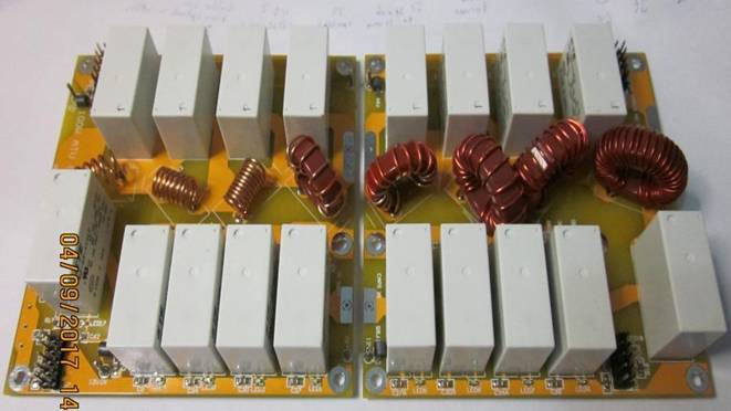
On the bottom of the yellow "RF" boards are some of the 3kV rated tuning Capacitors:- (I bought the smd caps from RS-Components(TM). Only a few values are required, as they are paralled in some cases.)
A new (draft) SWR PCB has been made, which should cater for both power versions of the project. It will use AD8307's. Gerbers not available.
Schematic link.
PCB overlay (some gremlins got in and C57 is missing from the "SWR" PCB.... it will be fitted as shown soon in series with R5) The actual PCB does NOT have coax connectors. It uses coax cable direct to the PCB.
How things are connected together. Drawing of the RF and Control boards showing typical wiring details. The SWR head is not shown but is connected to the Control board also.
SWR DECTOR BOARD DRAFT, FOR HIGHER POWER ONLY.
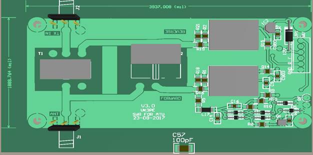
The PCB draft shown above made but found to have a problem. The input capacitor “C57” was left off the board! Stupid error. It should have been a higher voltage rated part anyway and the board could be used if a leaded high voltage 100pF cap is fitted over the board. The only board I have was home made. (Gerber's NOT available)
ALTERNATE DISPLAY TYPES:-
K3NG’s original Sketch is for a 2 line LCD module. You can use my control board with K3NG’s sketch with no changes required, as long as you use the serial I2C type RGB module he uses.
There are some alternatives though, if one wishes to modify the NANO sketch accordingly as most any I2C serial display could be used..
Please note, for now, I am not supplying alternative sketch changes, (see link ABOVE THOUGH) just use the K3NG original sketch and display type.
But, to show you some possibilities, for those skilled in C++, shown below are a full colour ‘Digole’ brand display and also a 0.96” OLED display.
A COLOUR DISPLAY
I happened to have a DIGOLE 'smart' display in the junk box, so thought it might be nice to use a colour display on the new ATU being built with the PCB's above. This display is smart in that it contains a Micro of its own and simple command strings can be sent from the Control board to make a nice display. The display I have is a non touch screen 2.2" type but there are others 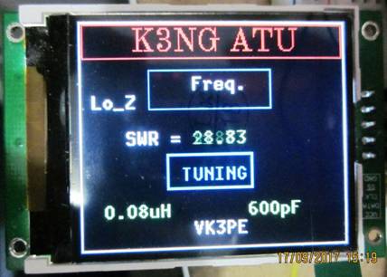 in the range with touch screen and up to 2.6" in size. For now I will stick with what I have available. NOTE, space in the NANO is a bit tight, so some K3NG options can not be used but this should not affect most people. One could switch to a MEGA I guess, with more space if it became necessary. My PCB's do not cater to this idea.
Here is a picture of the display being tested. (it’s not part of the ATU at present) The layout is tentative only at this stage and the colours are washed out from the camera. In actual use the colours are very good. Various sized fonts are built into the display plus one can upload more fonts to it. As the ATU tunes, the L&C values change on the display accordingly.
OLED DISPLAY
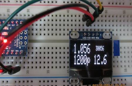
This OLED picture above, is an example only, using an OLED modified sketch. Layout of the screen and contents subject to change.
A FULLY BALANCED K3NG ATU ?
My original idea was to build a fully balanced ATU per K3NG’s information page. I actually had some PCB’s made for this and it comprises several PCB’s for the L&C sections. Obviously, two of each are required to do a balanced version. Shown are part of a balanced version, not completed. It uses 4 inductor PCB's and 4 Capacitor PCB's. No further info at moment.
NEW 11th May 2022 Fully balanced build by Simon, G0FCU
Simon recently completed a balanced version of the ATU, using my gerber files for the "RF" section. He has done a great job, click for detailed pictures.
25th Apr 2022
Hi Glenn,
After lots of trials and tribulations my K3NG balanced auto ATU is installed and working (see attached pictures).
I used an Arduino Mega and also added MQTT to the sketch so I can remote control and get status updates from it as it is installed outside. It's only just outside my shack window so was easy to get power and an ethernet cable to it.
Thanks again for the Gerber's.
73 Simon
G0FCU.
Below, are K3NG's prototype and his pictures, borrowed from the WWW. I hope he doesn't mind.
VK3PE is a member of Yahoo group "Radioartisan" that covers his various projects. The display shows final SWR (top left) the inductor and capacitor values and the approx. frequency. (The ATU remembers past ‘tune’ results)
K3NG ATU, Links:-
Firmware K3NG
Original K3NG Schematics
K3NG Youtube video demo
Yahoo Radioartisan group.
Adafruit I2C adapter board for standard 2x16 LCD modules
Arduino. There are a number of Arduino boards, but I used the NANO version on my control PCB, available either as an original part or copies from many eBay vendors.
DISCLAIMER !
This material is presented in good faith and based on the original work by K3NG.
No guarantee is made by vk3pe that this version works in an identical fashion to the original.
This page was created on 4th Sept 2016 by VK3PE
Last updated on
September 1, 2022