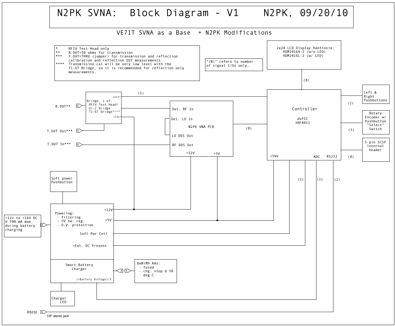
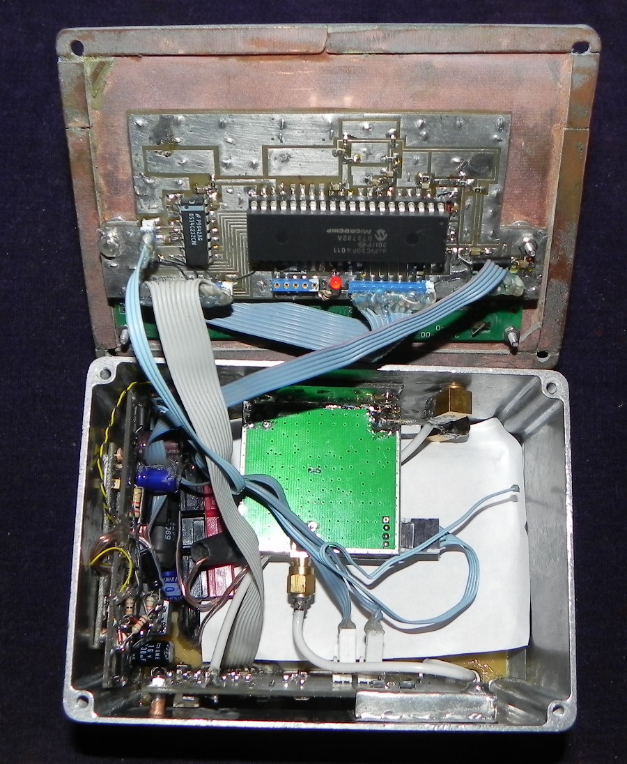
Here are some of the changes that I made to Lawrence's design:
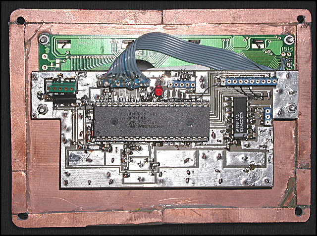
- RFIV Test Head instead of a T1-6T bridge and the bridge type is software selectable to be one of: RFIV test head, matched Hi-Z bridge, Lo-Z bridge or T1-6T bridge.
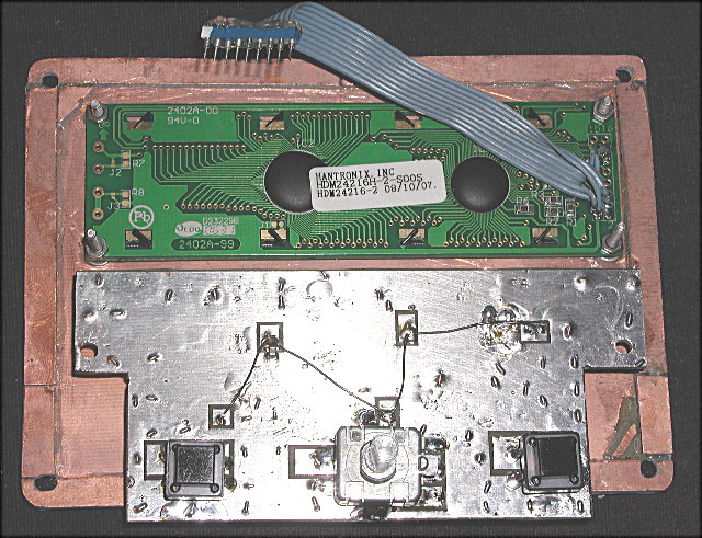
- Soft power control where the toggle switch in the pixes below was later replaced with a pushbutton. This also includes an inactivity shut-down to conserve batteries and a low voltage shutdown to preserve accuracy (and batteries).
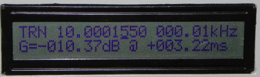
- Provisions for transmission measurements including group delay.
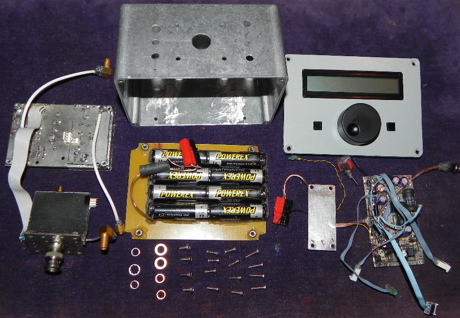
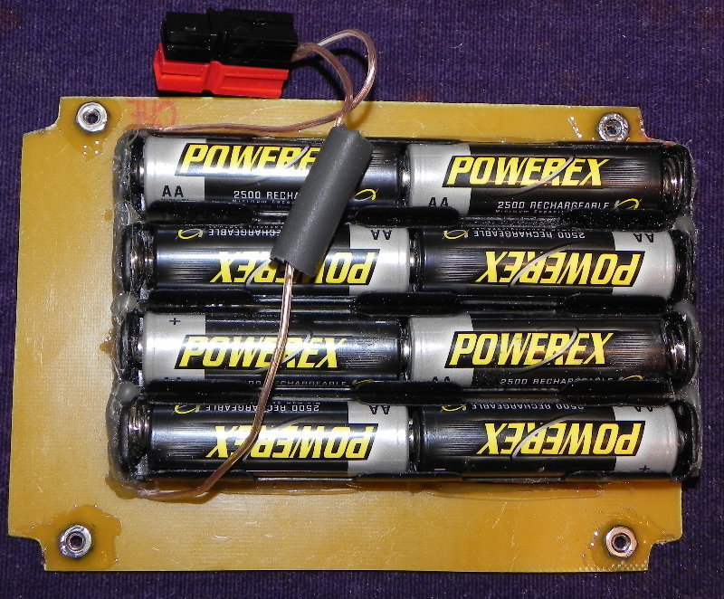
- Internal smart battery charger.
- 5V switcher to conserve batteries and minimize internal heating.
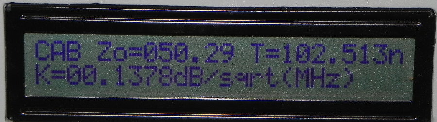
- Coax cable parameters.
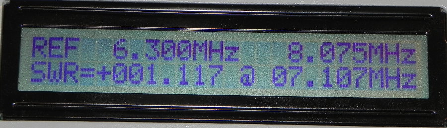
- Search a user specified frequency range for minimum SWR Code updates to support these and other changes.
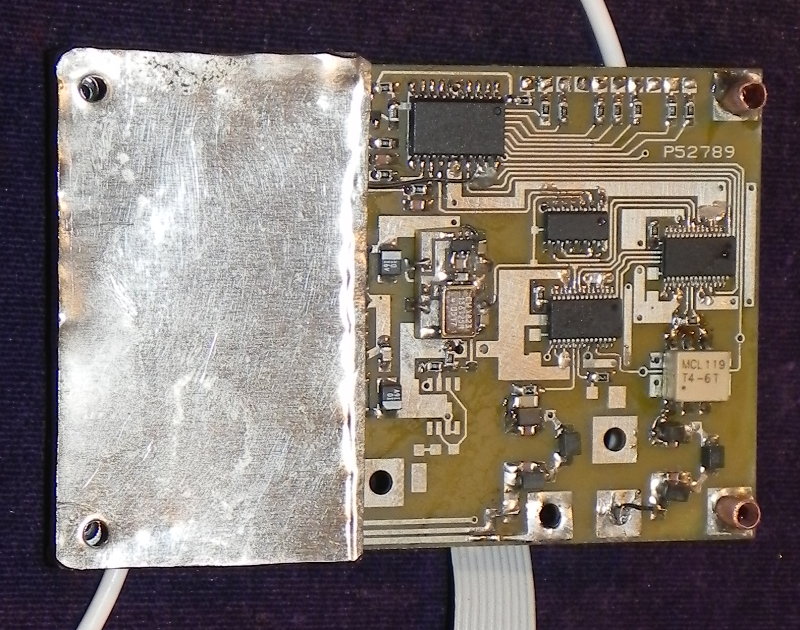
With 50 ohms as the reflection DUT (R.DUT), the transmission DUT sees a nominal 50 ohm load (as needed) and the RF DDS provides the nominal 50 ohm source impedance. At the same time, both the RFIV Test Head and the matched Hi-Z bridge provide relatively low insertion loss with the 50 ohm reflection DUT unlike the T1-6T bridge which is balanced with the 50 ohm reflection DUT present.
For reflection measurements, a coax jumper is used between the RF DDS and the RFIV Test Head input. This coax jumper is also the transmission thru calibration standard.
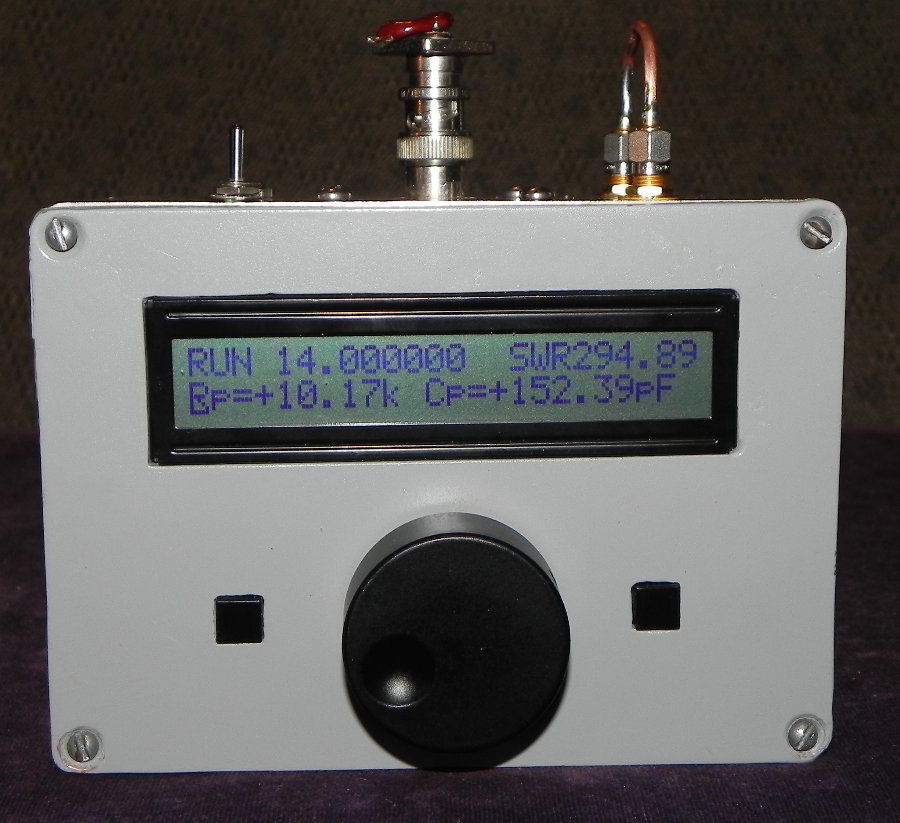
The above configuration and other features of the N2PK SVNA can be seen in the following block diagram: