This is a copy of N2PK's website. Paul has decided to delete his website (See N2PK-VNA on Groups.io message #5, Jan 2020) from ~Feb 2020.

Paul has made availalable a ZIP file of his entire web site, which has been uploaded as is, no changes made except for this preface. <vk3pe>

Contact Paul at https://groups.io/g/N2PK-VNA


N2PK's Amateur Radio Projects Page

I'm Paul and my amateur radio callsign is N2PK. I enjoy designing and building (homebrewing) my own equipment. There are only two projects so far, but others will be added as time permits:
Vector Network Analyzer (VNA)
Standalone VNA (SVNA)
HF Forward Power & Return Loss (SWR) Meter


Vector Network Analyzer (VNA)

This is a homebrew VNA capable of both transmission and reflection measurements from 0.05 to 60 MHz, with about 0.035 Hz frequency resolution and over 110 dB of dynamic range. Its transmission measurement capabilities include gain/loss magnitude, phase, and group delay. Click to enlarge
(Click on plots to enlarge.)
Its reflection measurement capabilities include complex impedance & admittance, complex reflection coefficient, VSWR, and return loss.
Unlike other impedance measuring instruments that infer the sign of the reactance (sometimes incorrectly) from impedance trends with frequency, a VNA is able to make this determination from data at a single frequency. This is a direct result of measuring the phase as well as the magnitude of an RF signal at each test frequency.
Click to enlarge

With optional narrowband extensions, this VNA can function through 500 MHz with some degradation in performance. Its custom software operates on DOS and Windows based IBM compatible PCs and communicates with the VNA through a parallel port. There has also been an adaptation of the design to the USB port by Dave Roberts, G8KBB. The VNA is aimed at the serious experimenter with, at least, a basic understanding of transmission lines.

Some Plotted Test Results

Here are some plots of measured impedance, gain, phase, and group delay results collected with this VNA and its software to illustrate its capabilities.

Smith Chart (Impedance Plot) of my 20 meter Attic Dipole

Smith Chart of a 20 meter Bandpass Filter

Smith Chart of a Nominal 9 MHz Quartz Crystal

Gain/Phase Plot of a 3.758 MHz SSB Crystal Filter

Passband Gain/Group Delay Plot of a 3.758 MHz SSB Crystal Filter

Gain/Phase Plot of an 80m Bandpass Filter with AM Broadcast Band Rejection
(This test example also illustrates undesired harmonic mixing and how it is substantially improved.)

PC File Test Data

The programs that generated the plots above also store the numerical test data in files on the PC for other uses. These data files can be imported directly into common spreadsheet programs, such Lotus 123 or Microsoft Excel, for viewing, user computations, additional analysis, or plotting.

The files are also readable by most text editors. Within a text editor, columns or regions of data can be selectively copied and pasted into e-mails, other documents, or programs such MathCAD or spreadsheets for additional analysis or plotting.

These files can also be optionally named by the user to aid in organizing the data.

Some Correlations with Commercial Test Equipment

Here are some correlation test results for the same Device Under Test (DUT) using both this VNA and commercial test equipment.

Correlation Between an N2PK VNA and an HP8753C VNA - Reflection

Correlation Between an N2PK VNA and a Boonton 250-A RX Meter

Correlation Between an N2PK VNA and an HP 4195 VNA - Transmission

(More coming...)

Publication Info

The N2PK VNA has been described by Pat Hawker, G3VA, in the Sept. 2004 issue of RadCom (Radio Society of Great Britain).

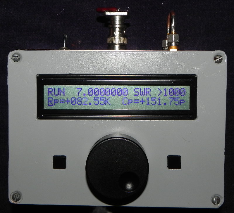
In addition to the VNA in the Sept 2004 isssue of RadCom, you will also see a reference to the "The N2PK power / SWR meter" which is described below.

Pat devotes almost one page of his four page column in this issue to the VNA and features the VNA block diagram.

The above RadCom reference is not available online.

Ian White, GM3SEK, devoted his entire Oct. 2004 RadCom "In practice" to the N2PK VNA:

http://www.ifwtech.co.uk/g3sek/in-prac/61_62_radcom_oct04.pdf

The Oct. 2004 RadCom front cover also featured a photo of Ian's VNA.

A highly processed photo of the VNA PCB around the RF DDS also appeared on the cover of the RSGB 2003-2004 Annual Report.

Bob Cerreto, WA1FXT, wrote an article about his N2PK VNA in the January 2006 Bacon Bits Quarterly Newsletter:

http://www.fpqrp.com/BBITS/BBQ0106.PDF

Bob's article also appeared in The QRP Quarterly, Spring 2006, published by QRP ARCI.

Giancarlo Moda, I7SWX, wrote an article in the April 2004 issue of Radio Rivista, an Italian publication, titled "IL VECTOR NETWORK ANALYZER DI N2PK".

The N2PK VNA is also discussed in the 4th Edition of "Low-Band DXing" by John Devoldere, ON4UN, and is available from ARRL and RSGB. See Section 3.6.9 on page 11-34. However, there are some corrections needed:

  1. The URL to this website is incorrect. It should be "http://n2pk.com".
  2. To my knowledge, there is no commercial effort underway.
  3. In Section 3.6.10, there is an implication that the N2PK VNA, with its narrowband detector, suffers from "alien-signal overload" in the same manner and extent as other instruments which typically have wideband detectors. A simulated test using the N2PK VNA, approximating John's 160m large antenna measurement with a strong AM BC "alien" or "ambient" signal present, yielded the following result:

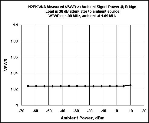
    As can be seen, the N2PK VNA is essentially bulletproof up to +10 dBm of ambient signal @ 110 kHz away from the desired signal. If needed for extreme cases, higher levels of ambient immunity can be secured by combinations of various means: a) increased (desired) generator signal, b) added attenuation between the bridge and the detector, c) a high-pass, bandpass, or notch filter between the bridge and the detector, or d) a similar filter between the bridge and the antenna. If the instrument is calibrated with the filter in place, then even quite substantial amplitude or phase errors in the filter will not affect the measurement.

    Most of these means can not be used with other instruments commonly available to the amateur radio community due to design limitations.

    As the frequency difference between the desired signal and ambient signal is reduced, the ambient immunity of the N2PK VNA is expected to decrease as the ambient signal falls within the detector bandwidth, which is 5 Hz at 3 dB down for the orginal "slow" detector and rate dependent for the "fast" detector. Time permitting, more about this may be covered at a later date. However, it is not a particularly pressing issue as no ambient signal problems with the N2PK VNA have been reported to date.

VNA Architecture and Build Info

This VNA, the majority of which occupies a 2.5" x 3.8" printed circuit board, is neither complicated nor expensive to build. It can be replicated by anyone with moderate skills in surface mount technology.

To read more about the N2PK VNA architecture and how to build it, click here.

Home


N2PK Standalone VNA - SVNA

This project uses a single fast detector N2PK VNA with a local controller, an LCD display, a rotary encoder, and three pushbuttons as its primary user interface. A PC is not required and it can be powered from either internal batteries or an external DC supply. It is based on a design by Lawrence, VE7IT, with several added features including an RFIV Test Head for improved accuracy and calibration stability as well as provision for transmission measurements with an optional display of group delay. Click to enlarge
(Click on pictures to enlarge.)
As there are only the schematics, some pictures, and code but neither PCB artwork nor even a parts list in what follows, duplication of this project is not for the faint of heart! For those of you interested in building something similar, I would suggest a slightly larger enclosure with a trapdoor in the back for battery removal and also combining the power and battery charger functions onto one PCB. My build uses an original N2PK VNA PCB which is no longer readily available. I would guess that one of Ivan's (VE3IVM) current N2PK VNA PCBs could be adapted by eliminating one detector where space is tight. Click to enlarge

To read more about the N2PK SVNA, click here.

Home


HF Forward Power & Return Loss (SWR) Meter

This project is a meter that is placed in a 50 ohm coaxial transmission line between a transmitter, operating from 1.8 to 30 MHz, and an antenna or an antenna tuner as shown here. Click to enlarge
(Click on pictures to enlarge.)

The circuitry has been added to an MFJ-948 Antenna Tuner (not "pure" homebrewing!). It uses the existing meter with a pair of modified scales. It can be easily adapted to virtually any coaxial line environment.
Click to enlarge

To read more about this meter, click here.

Home

Please feel free to contact me with any comments or questions at:

Contact Paul at https://groups.io/g/N2PK-VNA

73,
Paul Kiciak, N2PK

URL: http://n2pk.com/index.html
Last updated: 20 September 2010
Copyright © 2003 - 2010