 The KEY output stays high for transmission duration
and enables the 12v to the RD16HHF1.
The KEY output stays high for transmission duration
and enables the 12v to the RD16HHF1. Last updated on April 12, 2022 Added builders Pics.
New April 2022 Mikko, AB6RF's build
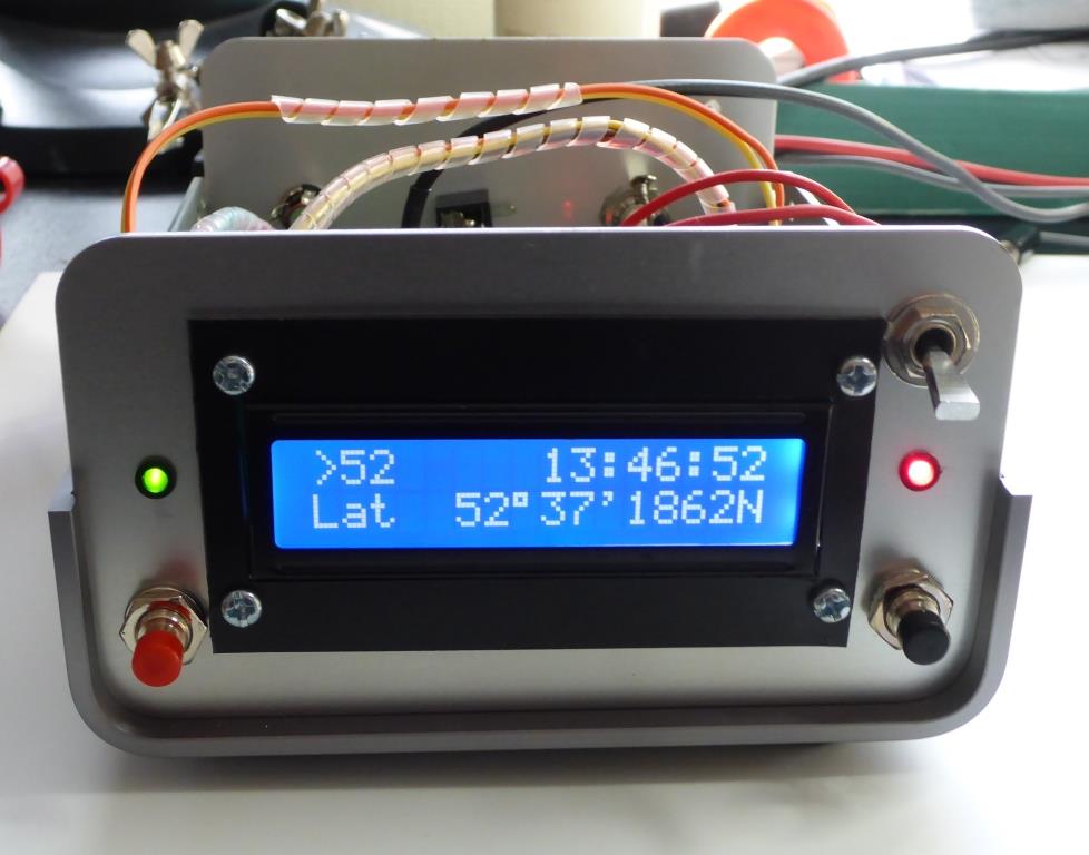
October 2020, Dave, WB4KDY's build.
Recently, I have become interested in WSPR mode and using my other project, the Hermes-Lite SDR in Rx mode, logged quite a few stations all over the world. The bug then shifted me to try transmitting also and rather than tie up my Hermes with a PC running 24 hours a day, I decided to buy the very economical Ultimate Transmitter kit from Qrp-labs.
This little kit (Ultimate 3S from http://qrp-labs.com ) is great, very good value and excellent support. There are a number of options available but I built mine as a single band, 30M. The Transmitter outputs approx. 200mW and with this 'flea' power, signals can be heard much further than one could imagine. After running it like this for some weeks I decided to up the power to 5 Watts which is about the maximum level used. Maybe not the right thing to do but I was curious as to how increased power might work.
A search of the web found a number of simple PA's of this power level using various devices. I opted to build mine using the RD16HHF1 which is a popular device used in many amplifiers upto the 20W pep level, however they use two in push pull. A single device can be used for around the 4-5W level, some builders even claiming upto 7w or so. This one will put out 4 to 5W driven from the Ultimate Tx. (checked on 30M band)
I don't claim any originality for the end design. It's part based on web searches and also the PA used in the Hermes Lite project. The only major change from the 'norm' is the use of a series FET in the supply line, to enable the PA, keeping standby current to a miniumum. Almost zero in fact. This input to the PA PCB comes from the "KEY" output of the Ultimate S3 board. The KEY output pin is located near the edge of the PCB adjacent to the BS170 FET's. (picture of part of Ultimate S3 from qrp-labs web page)
The KEY output stays high for transmission duration
and enables the 12v to the RD16HHF1.
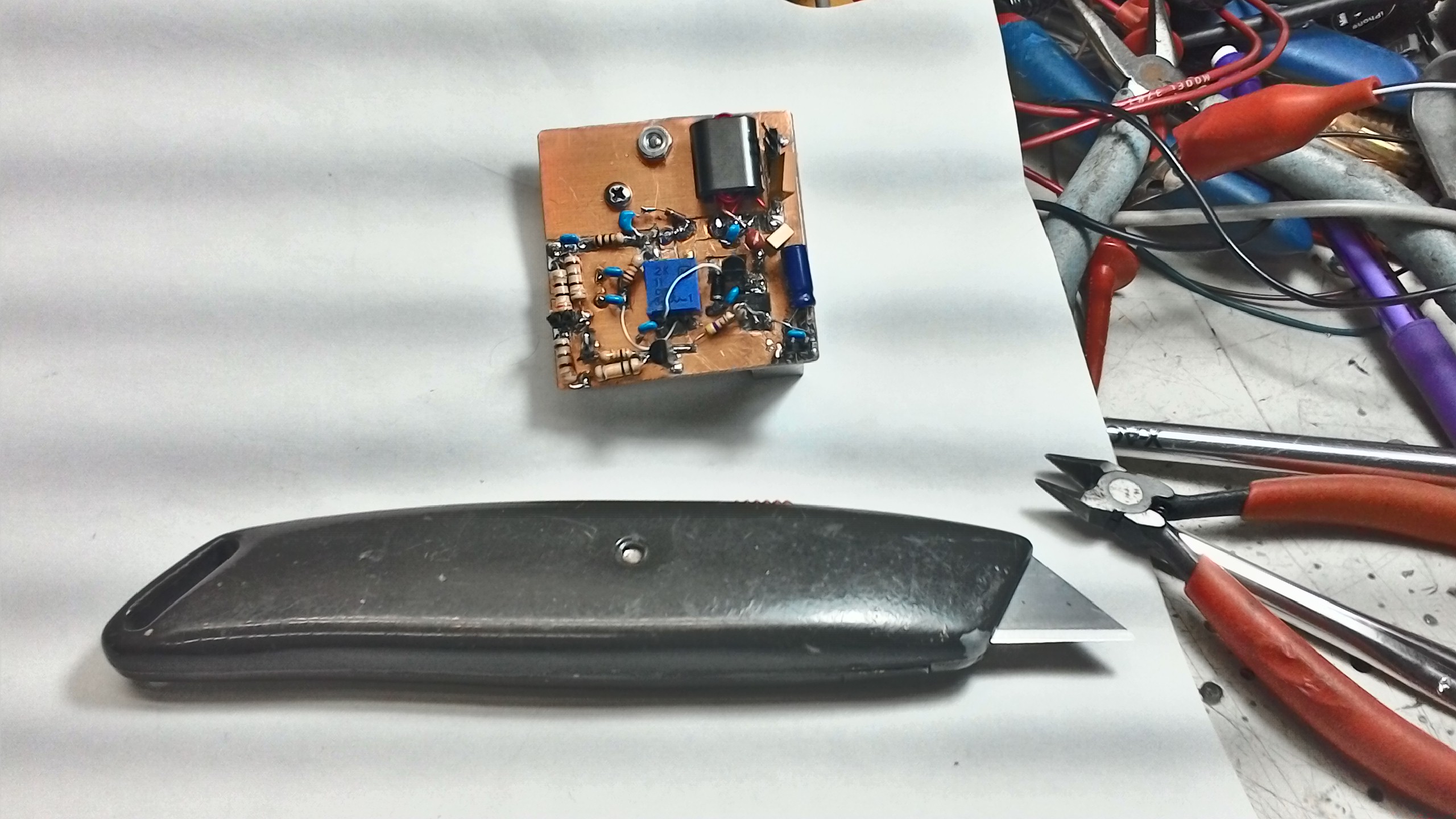
Originally, I lashed this up on an an old piece of PCB material and it has run with no problems for several weeks. Then, I decided to pretty it all up and make a proper PCB for it. I used an eBay supplier to make the PCB's for me, and duly received 5 pieces in the mail.
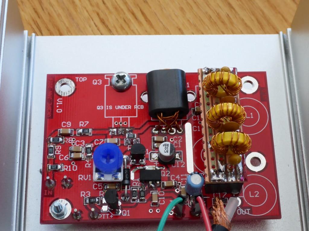
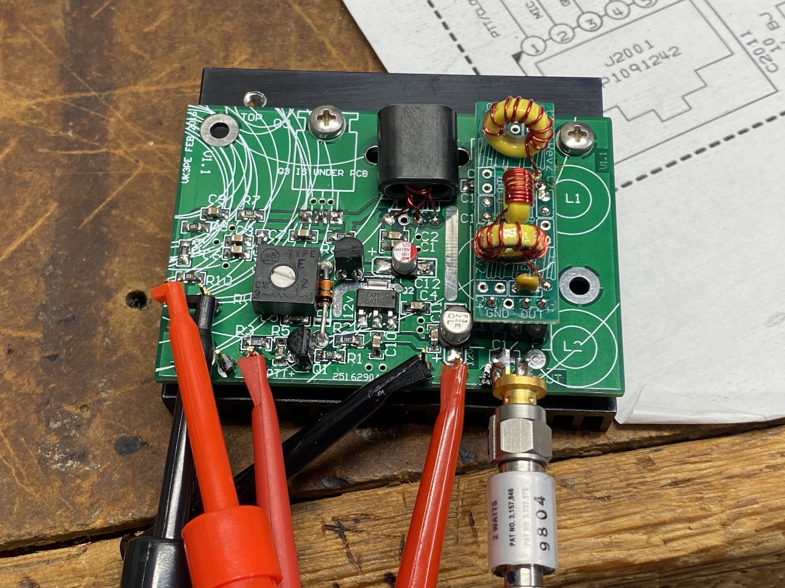
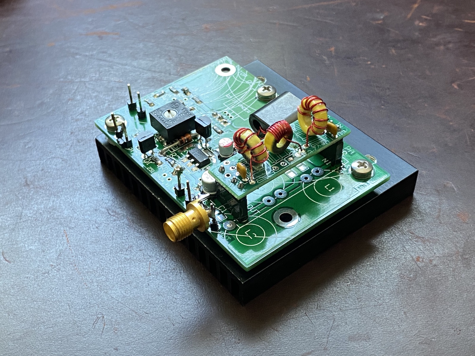
To make things 'simpler' I designed the PCB to use a plug-in LPF PCB from QRP Labs but also the LPF can be fitted directly to the PCB. I used T50 cores here.
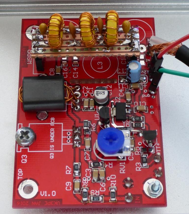
Left using QRP Labs plug-in LPF, Right, on board LPF. The PCB is approx. 73 x 50mmm in size.
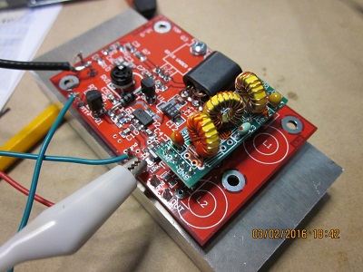
The amplifier needs a decent heatsink. I used a piece of aluminium about 15mm thick that I had, drilled and tapped to take the RD16HHF1 and PCB itself. It barely gets warm in the typical 2 minutes ON, two minutes OFF of WSPR mode. It might also fit onto an old PC Processor heatsink, although I don't have one to check.
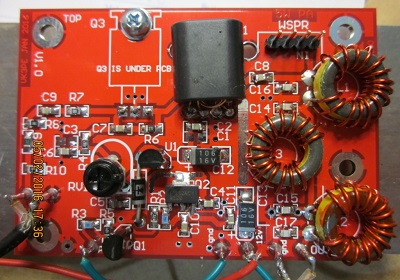
I made a small mistake on the PCB, placing a wrong footprint for the NDT2955 part, Q2. (located on RH picture, roughly in lower center of picture. It can still be fitted as you can see if done careully. I have now corrected the artwork for any possible future order.
Contrary to the Qrp-Labs kits, this PCB mainly uses SMD components. Don't let that scare you, SMD is a simple process with tools you already have. "0805" sized parts are used which are easy to handle. The RD16HHF1 device is a TO-220 sized part and is mounted under the PCB with the leads bent upwards to fit into the PCB holes. Use a light coating of heatsink compound when mounting. No insulators are required. Suitable spacers need to be used to take up the 'gap' to the bottom of the PCB and also for the four mounting holes. Proper spacers or washers, nuts etc can be used.
Setting Bias:
Before powering up the board, rotate the trim pot fully anti-clockwise. Do not apply any drive to the input. Use a power supply with Current Meter and power up the PCB. Current should be virtually zero. Apply 12V to the 'PTT+' input and then rotate the trim pot slowly until ~600mA is observed on the meter. This is now the bias level (or Iq, more accuretly) of the RD16HHF1. The amplifier is now ready for use. With the typical 180mW or so from a WSPR Ultimate Transmitter, the output of the amplifier should be 4-5W. (tested on 30M band with typical 180mW drive from single BS170 in WSPR board, at 5v)
Sweeping the amplifier for frequency response (without LPF of course) is shown below. The left picture is the low frequency end (0 - 10MHz), the right hand picture is the upper frequency 0 to 100MHz. I didn't plot upto the 2M band, but its probably still usable for 2M WSPR. (subsituting the FET for the RD16HVF1 may be better for 2M band) The LPF though may not be optimum on the PCB due to tracking etc. I have only tested the 30M band (shown) as that is the most popular WSPR band.
50MHz is down by about 1.5dB compared to 2MHz

Below, is the spectrum to 30MHz showing the 2nd (Marker #2) harmonic of the 30M band is down by ~68dB compared to fundamental. (#1).
The levels below are with bias of 600mA. This results in best harmonic suppression. Lowering the bias to 100mA for example, leaves the 2nd harmonic at -57dB. (11dB worse) The choice is upto you.
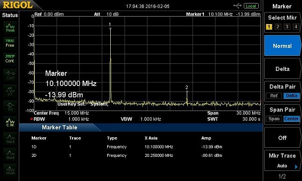 There was a 50dB attenuator in line to the SA to prevent damage to it.
SCHEMATIC updated 250216
Previous SCHEMATIC (pdf) See notes above for bias setting.
Bill of materials (Excel) (Right click mouse to download)
PCB stuffing:- component overlay by value
All components should be easy to get from the usual suppliers. I used Farnell™ (Element14™ in some countries) for most of the SMD parts and www.minikits.com.au supplied the RD16HHF1 device. In the USA, www. RFparts.com have the FET. In Europe, I don't have supplier name but am assured that they can be bought easily there.
As noted above, the PCB can be fitted with the LPF board kit from QRP-labs.
If anybody wishes to experiment and duplicate this PCB, I can supply a pdf of the copper for DIY, actual size, or possibly Gerber files to have them made by a PCB house. In which case you will end up with probably 5 pieces. Maybe share with some friends. The PCB's shown here are V1.0 that had small pads for Q2. The Gerber files have been corrected and are now V1.1.
I have no affiliation of any sort with this company, but used www.elecrow.com for the PCB's. Cost (in 2016) was US$11.50 plus shipping costs. Since then the cost seems to have risen a few dollars. (In VK our exchange rate is poor, so my total cost was about AUD$24 for 5 PCB's, ie AUD$4.80 each) You may have your own favourite PCB house.
I had THREE spare PCB's, but
SORRY, ALL NOW GONE pcb's only available (no parts
supplied, just pcb) if anybody would like to duplicate this project.
The above was written long ago when Chinese PCB supply houses were not so common. These days you can get 5 boards for US$5 or even less, plus postage or DHL shipping. eg JLCPCB.COM or ALLPCB.COM to name a couple. NOTE I have no affiliation or financial arrangement with any company.
Chris, G0IMX, has also built one of my boards. His Amp. is also working very well, in bench testing so far.
Chris has made his own LPF, as a plug in.
Feb 2016 <edited version>
Hi Glenn,
Well I've now done most of the building of the PCB. The only small problem
was lack of a 270R smd part which I solved with three smaller bits in series
(220R+0+47R) which looks OK - just a bit weird.
I worked out how to fit the NDT2955 which was not a problem. I used the suggested
two turn on the BN43-202 core.
My case is 3mm thick aluminium and definitely nowhere near your 15mm brick so
I am waiting to see what tests show with temperature checks.
(Much later) Initial tests showed no output and after removing power I tested
for continuity around the output filter which uses the QRP-Labs low pass filter.
Solved by linking the output pin of the filter socket to the PA output pin under
the PCB. I suspect this had something to do with your original design for the
filter components on the PCB. (see updated Sch for details, vk3pe)
So I am now starting the hardware bit - sockets and plugs for linking the U3S
and the Linear. I am envious of your metalwork on the STAR project. I don't
have a workshop or the tools to attempt that sort of chassis building.
Good news! My rough graph would seem to suggest it could be 7W+ which is possible
as I had previously changed the input attenuator to 4dB. I think I might just
back off the U3S bias and carry on with tests.
No metal bashing today as I have a cold at the moment and didn't feel up to
working in the freezing temperatures in the garage.
73 Chris
G0IMX
15th March 2016:-
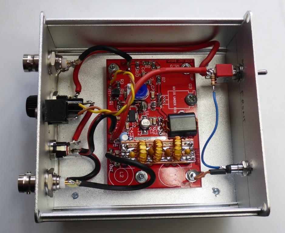
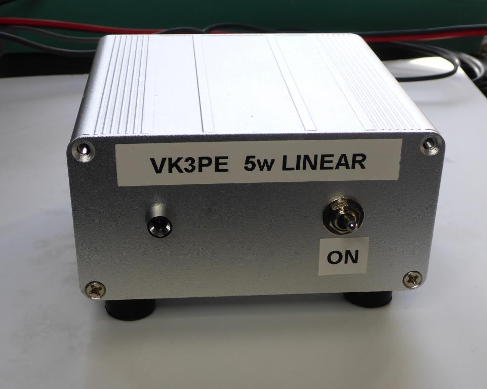
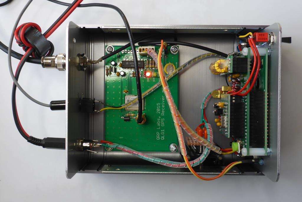
Chris has made a very nice job of his WSPR station. Pictures below.
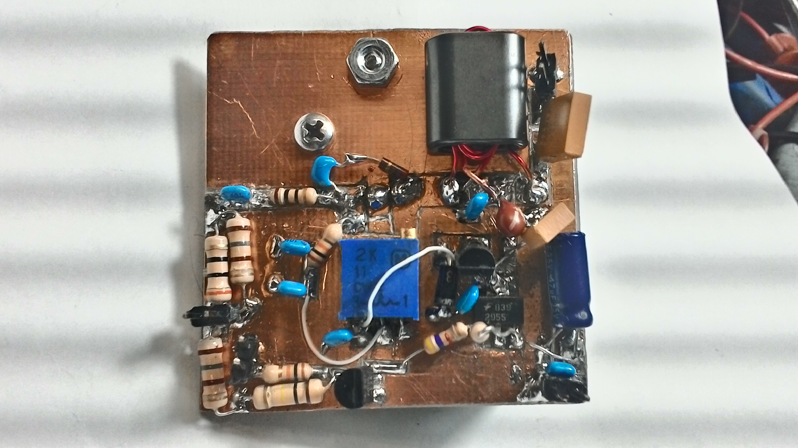
Dave, WB4KDY, built his version using a knife and blank PCB material.
14th April, 2016: Ross, has identified some potential SMD inductors some may wish to experiment with to fully "SMD" their build. Perusal of the RS-components web site may find more values. <vk3pe>
G’day Glenn,
I was going through the RS Component SMD inductors and found a bunch that might
be very useful for SMD LPFs
the values needed would be 1024nH(16t) and 900nH(15t)
One can get 1000nH that are good for quite high current so should not saturate in the PA.
http://au.rs-online.com/web/p/multilayer-surface-mount-inductors/7568459/
http://au.rs-online.com/web/p/multilayer-surface-mount-inductors/7568519/
820nH
http://au.rs-online.com/web/p/multilayer-surface-mount-inductors/7568519/
Clearly, these inductors have a 20% tolerance but could be quite elegant on the SMD PA board.
73
Ross
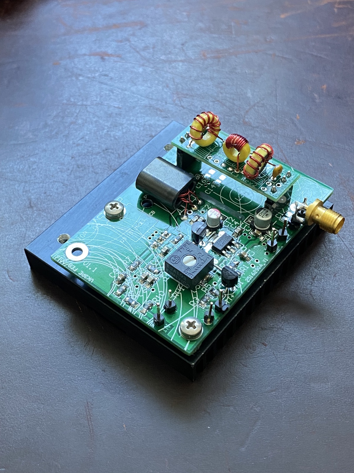
NEW April 2022, Mikko, AB6RF, sent me some pictures of his build, from my Gerber files. As you can see, there are some strange lines on the overlay of his boards, apprently some sort of error by the PCB supplier, as the same Gerbers have been used by other builders with no problems.
Apart from that, Mikko reports the build went well and is currently undergoing testing. Mikko's project uses a Rasberry Pi as the source of WSPW, driving the 5W PA, Mikko repors that he gets about +21dBm from the Pi and almost +36dBm from the Amp stage. (about 3.5W)
Click pictures for larger size.
------------------------------------------------------------------------------------------------------------
This information is presented for experimenters and DIY Amateur Radio constructors.
NO kit, or parts, are offered by vk3pe, for this project.
This RF amplifier is intended for licenced Amateur Radio use only. Use by unlicenced persons may constitute an offence in some juristrictions.
Disclaimer:- All results shown above, are for the PCB I had made and tested. Your results may vary.
Page last updated on April 12, 2022
Page created on 6th Feb, 2016 by vk3pe
(email address is at www.QRZ.COM )
![]()