Combo PIC-a-STAR
build and interconnection pictures
Last updated Dec
7th 2013, RS232 test cable details added.
17th May, 2013, some
"{P2" pcb version info added}
These are pictures of the 1st build of a "P1"
version PCB, to give builders a better idea of the connections which have to
be made. The P2 & P2a version is near identical, just
a few of the minor errors of P1 corrected. The pictures show the 1st
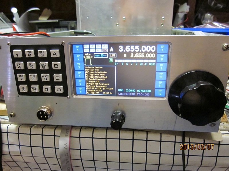
test of the Combo P1 receiving signals, not the final unit. Basically several
cables are needed:-
1) 20 way IDC cable which runs from top to bottom,
oriented as per the pictures below.
2) 4 way cable carrying the DSP 15KHz signals
from top to bottom, located near the DSP section. See text near last picture.
3) Four co-axial cables under the PCB's connecting
the top and bottom boards. There are numbers printed under the PCB's which
show what points each of the cables connect to. The best way to run these
is to bring them towards the front of the sub-chassis as you can see. Best
cable to use is miniature teflon covered co-ax. Often found on eBay in short
lengths. eg search "K02252D" which is teflon cable 3mm OD.
Even better is the smaller, as more flexible, is (~1.8mm OD) RG178
Teflon cable that is item number 380576703742.
(Feb 2013) This vendor is selling 4 x 18" lengths which should be about
right, although might be better to get two lots.
Update 17th May 2013:-
also check ebay item 150498248282
This seems very cheap for the RG178 cable in a 50 foot length. The ebay
link may be invalid now but a search for RG178 should find it.
Your local Ham radio supplier may have some RG178
also. Or, at a pinch, use RG174.
4) Microphone and PTT cables run under the PCB
to your chosen Mic. socket. (not shown in these pictures) Use shielded audio
cable.
5) Ribbon cables to the LPF (not shown), the TFT
display and keypad. The latter come from the Trxavr controller (ATMEGA2560
area)
6) You will also need a test cable for the RS232
jack, for testing using Peter's QBASIC software. The cable will have a male
3.5mm plug on one end and a DB9 socket on the other. Refer to schemacts, "DSP
MB" area. If in doubt, email me for more info.
There is also an integration
drawing in diagramatic form, here.
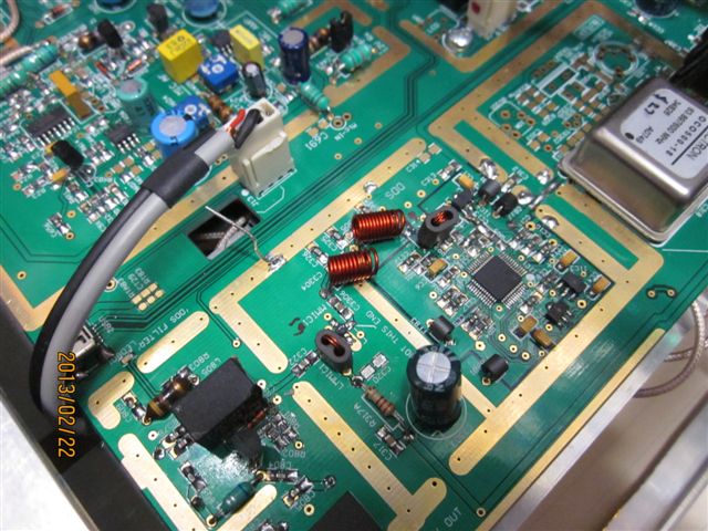
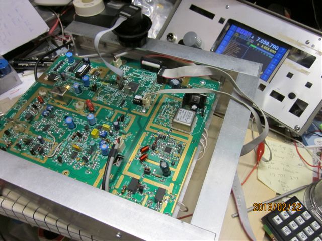 BOTTOM view, shows cables (note some ribbon cable here go to the keypad and
TFT on the bench !)
BOTTOM view, shows cables (note some ribbon cable here go to the keypad and
TFT on the bench !)
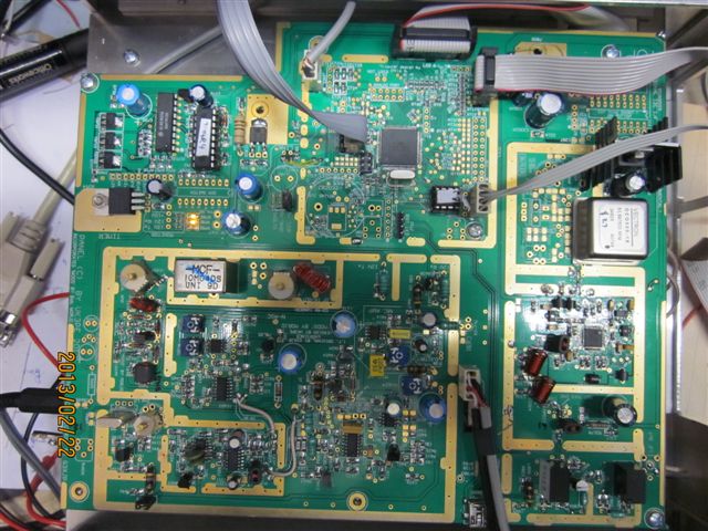 Overhead view of above picture. NOTE orientation
of the 20way IDC at the top.
Overhead view of above picture. NOTE orientation
of the 20way IDC at the top.
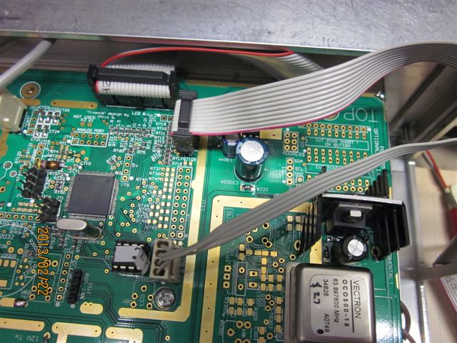 More detail of the 20 way IDC to bottom PCB and also the keypad. Lower cable
is to TFT. NOTE: additional heatsink on the OCXO
regulator here. (there are two back to back heatsinks) Not fitted in picture,
are encoder and tuner controls.
More detail of the 20 way IDC to bottom PCB and also the keypad. Lower cable
is to TFT. NOTE: additional heatsink on the OCXO
regulator here. (there are two back to back heatsinks) Not fitted in picture,
are encoder and tuner controls.
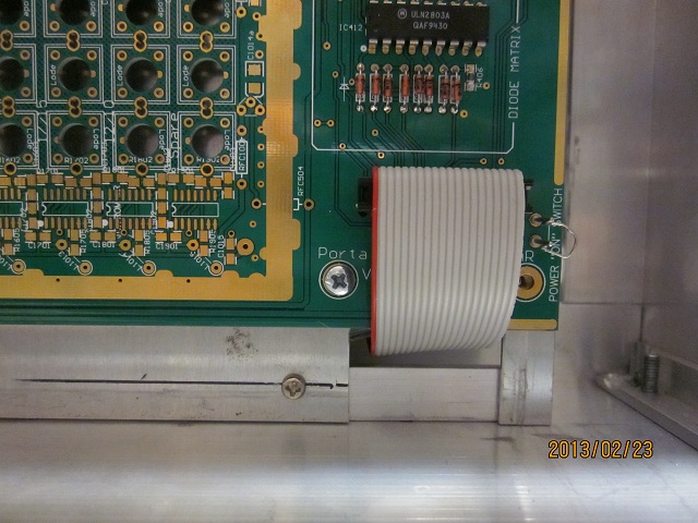 This picture shows the other end of the 20 way IDC cable. NOTE
the pin 1 end (red stripe) on both ends of the cable should be as shown in the
pictures !
This picture shows the other end of the 20 way IDC cable. NOTE
the pin 1 end (red stripe) on both ends of the cable should be as shown in the
pictures !
 This is the 4 way cable to mating connector on the other PCB. It's a 1:1 cable.
VK3PE reccomends using two core shielded 'audio' cable and also a single core
shielded cable to make the assembly. Make the cable long enough to allow each
of the PCB's to be removed if required for testing. Although there is a hole
in the PCB for the cable to run through, VK3PE found it better not to use the
hole on this side of the radio.
This is the 4 way cable to mating connector on the other PCB. It's a 1:1 cable.
VK3PE reccomends using two core shielded 'audio' cable and also a single core
shielded cable to make the assembly. Make the cable long enough to allow each
of the PCB's to be removed if required for testing. Although there is a hole
in the PCB for the cable to run through, VK3PE found it better not to use the
hole on this side of the radio.
Once completed and all
software loaded, a jack with the active pins connected using a 1k leaded
resistor should be inserted into the 'serial' socket adjacent to the rear
slide switch. This allows the S'meter and other data to be correctly displayed
on the TFT display. OR, a resistor may be fitted on the RS232 jack. Refer to
schematic for details.
NOTE: the
P2 & P2a version has this resistor fitted on the underside of the pcb
in the 'RS232' jack area. May 17th 2013
DEC
2013:- The RS232 test cable unfortunately is
different to that used by G3XJP on the homebrew PCB's. So, if you built H/B
pcb's and made up a cable for the RS232, it is different on 'P' version PCB's.
Details are in the Schematic file and also here, in
this drawing.
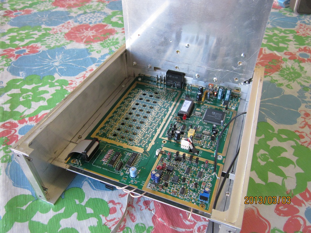
3rd March, 2013:-
This is the current state of the VK3PE build with the case, made from extrusions.
This build will be 20W PA only. Although, there
is space allocated on the rear, for the 140W PA later. The hombrew PCB in the
back is Ian's (G3VPX) PEAKSWR bridge which integrates into the Trxavr &
TFT display for on-screen power output and SWR.
As space is tight in this build, the PCB's are mounted
on a top "deck" which can be hinged upwards for access to the main
"P1" PCB's below. The top cover will just clear the LPF by about 5mm.

Below is the top "deck" hinged upwards.
Still not fitted are the front supports for this chassis.
You can also see the four co-ax interconnect cables,
wrapping around the central chassis. (the black coax cable on the right is temporary
only)
The VK3PE
build above does not yet show the fitting of shielding which is highly recommended.
The radio will function perfectly well as it is shown here, but for best shielding
and reduction of spurs. the shielding should be fitted, once happy with the
testing.
This
web page created for the Combo version P1 and later, the P2 version, PICASTAR,
on Feb 23rd, 2013 by VK3PE
Created on 23rd Feb,
2013,