STEVE G6ALU's 150W PA
This PA design is based on a Motorola® application note, AN762, modified by Steve (G6ALU) to use the SD1487 transistors which were available quite cheaply from Birketts in the UK.
*** As of late 2010 though, this source has dried up. You can of course use the original Freescale parts and also others specified on the Combo pages.
This PCB is no longer available from vk3e due to high local costs. An almost identical PCB thouh is available from www.communication-concepts.com (USA) They have kits of parts also available. To use with Picastar, a slight mod to enable switching will be needed.
This is NOT an official part of PICaSTAR.
This is simply a "blog" of my own PA assembly. Steve's own web pages take precedence.
VK3PE
Last updated, April 13, 2011 Tidy up only.
NOTE:- Text refers to the 1st run of PCB's. 2nd run (Combo vers.) has errors corrected.
Sept 2008, added info on C4
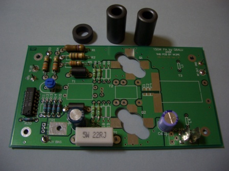
The Ferrites at left were bought from RS Components. They have to be bought in 5's for the tubes and 10's for the toroids. The balun core was bought from another vendor.
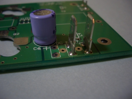
The holes for the spade lugs may be too small, depending on the type you buy. (on later PCB's his was corrected) In my case, I had to drill the holes out to 1.5mm then insert the lugs, and solder both sides.
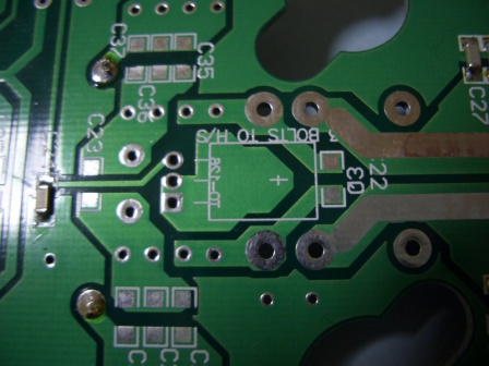
There is a hole missing for Q3 mounting. (on later PCB's his was corrected) This is due to a misunderstanding on my part, on how Q3 is fitted. I had thought it was bolted to the chassis only. In fact, the bolt must also pass through the PCB from the top.
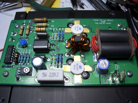
You will need to drill a 3mm hole in the PCB. DON'T drill it where the cross mark is on the Q3 outline. Drill it slightly to the left, in line with the larger holes to top and bottom of the picture, for the transformer (T2) fitted above. Check against your BD135 transistor, to ensure the leads will still fit the PCB, before you drill ! NOTE, the heatsink face of the BD135 goes to the heatsink ! Picture of a drilled hole in the picture to the right. Make sure you drill a smaller hole first, say 1mm or so, then increase the size up to 3mm in several steps. This results in a much cleaner hole in the PCB.
The transistor is eventually "sandwiched" under the PCB. The height of the PCB above the heatsink is determined by this transistor and the output transistors. Spacers of the correct size must be used under the mounting screws for the PCB.
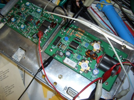
Left picture:- The pads to the right are for C22. Right picture:- I used parallel 12R to get the "5R6" value.
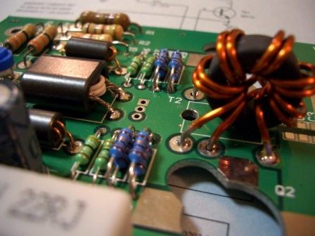
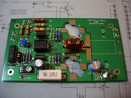
Above right you can also see the winding of T1 and T2. (T2 is not yet soldered in)
T2 is a bit tricky ! It is wound with 1.25mm wire in bifilar and it's quite difficult pull the 2 wires through. I resorted to winding one wire, a turn at a time, then the other wire. You need to form and pull the wires quite a bit in order for them to 'fit" close to the toroid. I thought I might break the toroid but it was fine. It's also a bit of a headscratcher to sort the wires for bifilar connection so take your time when doing this. I certainly did. I used the Beeper to confirm the connections also. The primary winding (1 turn) is on the left. The wire passes through the core once only. T2 needs to be mounted such that it is still possible to insert the screw for Q3 mounting later.
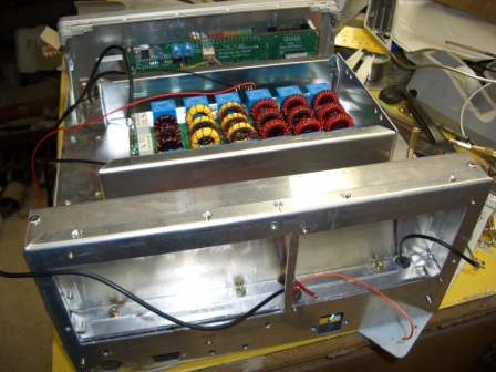
11th May, 2008 Moving along now. Have wound T3 also. I used some PCB material and cut the gaps with a hacksaw. Not pretty but quick. Could not get brass tube so drilled out some 6mm brass rod I had. In the pictures below, you can see the vertical cut in T3 (left side)
NOTE: If you use double sided PCB material as I did, the cuts must be on both sides of each piece !
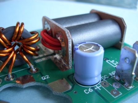
At the output end of T3, you need to scrape a little resist off the PCB, to tack down the end. Note that the end copper of T3 is also cut to isolate it from the PCB.
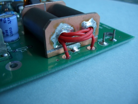
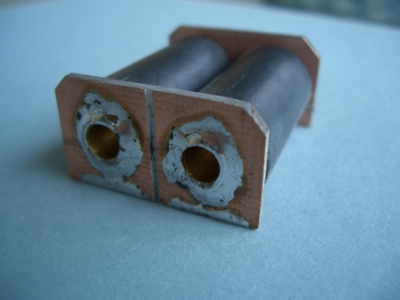
NOTE....C4 is mounted on the end of T3.
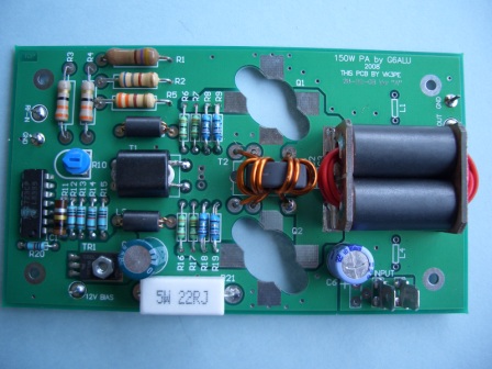
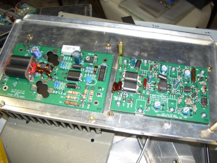
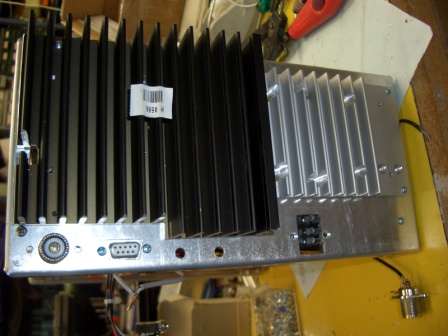
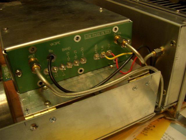
This is how my own PA assembly will look. 20W and 150W PA's side by side on the back panel. Both are inserted from the outside of the case for easier maintenance and assembly. There are two large rectangular holes in the rear panel, about the size of the PCB's. In the pictures, still have to drill holes for power input, RS232, antenna sockets etc.
This whole area will have a shield fitted over it. See later on this page.
15th May, 2008, almost done. Heatsink drilled and tapped for the PCB and transistor mounting. The bias supply was checked before soldering in the SD1487's. I trimmed the SD1487 leads back about 2mm with a pair of scissors before soldering them in.
18th May, getting impatient ! I want to try it out, so did a quick test with sig gen into the 20W stage at -28dbm and got around 112W output. Needs some decoupling of the power leads etc as everything is a bit touchy. The dummy load is getting VERY hot so something good is happening.
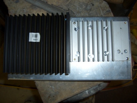
A lot of the (rainy) day was spent making a new rear panel and shield for the PA section. As you can see, there is a shield over the rear of the PA section. Both the 20 & 150W PA's are fitted from the rear of my STAR. You can also see the LPF behind. It is mounted in a hinged home made box. A cover will be fitted also and I think I will try to put co-ax connectors on each part, as I found some nice SMA cable assemblies at a recent rally (Hamfest)
22nd May, 2008: More Testing:
I have fired this lot up and it is producing lots of power but exactly how much I am not sure since I have neither a dummy load or a power meter. My 30W load quickly disintegrated ! I am going to investigate making a 200W load from some non-inductive resistors that Farnell sell. Will advise when I get some.
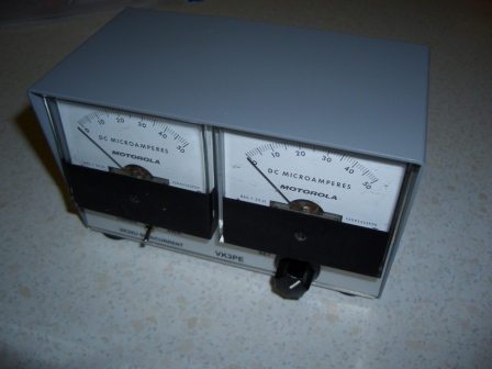
For the power meter, I saw an article on a line current and SWR meter in our local "Amateur Radio" magazine and built it up.
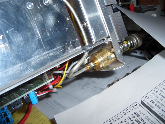
June 22nd, 2008. Mmmmmm......... integrating the 150W PA into my STAR, I was confronted with very bad RF feedback. This was traced to poor quality co-ax cable from the LPF Antenna connection down to the UHF (SO-239) antenna socket at the rear.
At a recent Hamfest, I picked up some very cheap SMA-SMA coax cables made with flexible hardline. I replaced the old cable with the new and also totally shielded the UHF socket by machining up a brass cover with a mating SMA socket on the inside of STAR and problem now solved !
NOTE: the LPF wiring has not been completed. It has been set for 80M only at this stage. The LPF is in the box with the PCB mounted on the end.
Early August, 2008, I still have the feedback problem ! OK at low power levels but something's not right. There is some 'modulation' of the DC input power lines visible on a Scope but I thought it was low enough to not be the problem but checking the 10V supply line, I can also see it there. I also get a distorted sidetone signal.
For the sidetone, I added a 10R in series with the 12v supply to the AF amplifier board and fitted a 2000uF cap at the amplifier. That fixed that problem. This was a suggestion from Milton Keynes radio club members.
For the power leads into my STAR, I use a 6 pin Jones plug on the rear (see pictures above). I split the connections so I now have a seperate DC feed from the power supply to the PA and one for the rest of my STAR. 10th Aug, 2008:- Testing on-air now seems fine. I had a very good report of audio quality and no sign of RF feedback like sounds.
I also finished the wiring of the LPF board.
11th Aug, 2008. A couple of people in the PICASTAR net (80M monday at 8pm) suggested there may still just be a hint of a problem on voice peaks, others say it's fine. I will look a bit closer though. At the time I was running about 140Watts.
Parts:
Schematics:
Component overlays:
Refer to Steve's parts list on his web site. (see Links on STAR group)
Ferrites:
Check messages 1331 to 1340 etc on the "homebrew_radios" reflector for sourcing of Mica caps and toroids.