|
|
TrxAVR-Picastar by G3VPX. These pages are by VK3PE for construction of the TrxAVRB I/F PCB's. (Page format shamelessly borrowed from Ian !) |
|
G3VPX's TrxAVR Interface web pages.
|
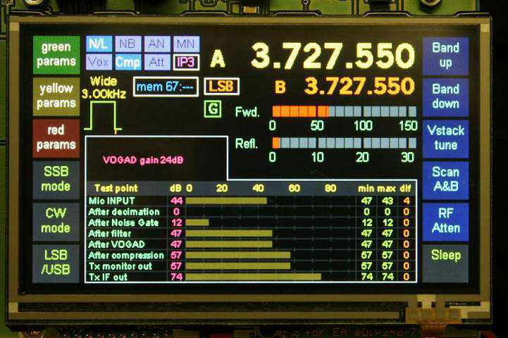
TrxAVR-Picastar provides an alternative controller and user interface for a Picastar Transceiver. It replaces "PICnMIX". Picastar is a very popular HF transceiver designed by Peter Rhodes, G3XJP, for home construction.
Picastar construction information, software, setup and
operational instructions are Errors on the PCB:- PDF file of this page for printing etc.
PLEASE read all of this information ! (report any errors or points not clear please to vk3pe#@bigpond.com) remove the "#" symbol from email address. Last updated on: August 26, 2009 Unfortunately, a number of errors have crept in on the PCB due to several factors. I am indebted to Paul Craven, for patiently going through his PCB and finding some of these. Most are fairly minor and just involve a wire link or so.
TrxAVRB section (central PCB on the Panel)
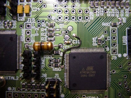
There is a missing ground connection (GND) to pin 11 of IC1 (Atmega2560) Fit a short wire as shown below from the via adjacent to pin 11 to the via above C10 which is at the top of IC1.
Missing ground on pins 25 & 26 of IC5 (under PCB) On top of the PCB, right hand side, fit a short wire from the via above R46 to the via below R42.
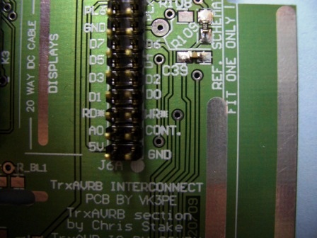
Missing track: There is a track missing from PL5 pin 5 (marked WR*) to the via just to the right of it. On the bottom of the PCB (not shown), fit a short wire between these two points.
Incorrect overlay: On the connector J6C on the bottom left of the PCB, the text "A0" & "RD" are reversed. You can scrape them off with a knife or use a marking pen to revise them. (not shown)
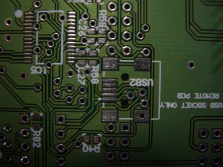
There is an error on the central "USB2" connector. This probably won't be a problem to most builders. There is no ground connected to the top pin. (the very centre of picture, just to right of "R58") This USB connector though is ONLY used if the central section of the PCB is removed, as per the information above. There is a ground hole just to the left side of C27 so a short near horizontal wire could be fitted. Normally, the other USB connector further to the right will be used, or a remote USB socket.
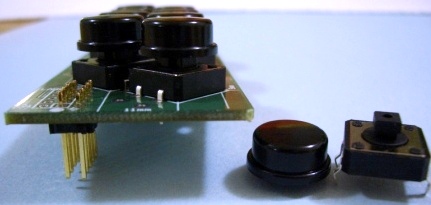
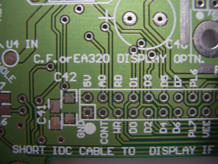
The 8 button keypad (right hand small PCB on panel) The holes for the 10 way IDC connector have been drilled 2mils (2 thousands of an inch) undersize. This does not sound like much but the connector will NOT go in. The best way to solve this problem is to use a sharp knife and scrape two corners of each pin of the connector a little, until it can be comfortably inserted into the PCB. Do NOT drill the PCB holes out as they are plated through holes and you will lose connectivity.
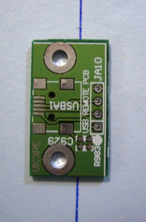
Remote USB board (top left PCB on panel) MAJOR PROBLEM WITH THIS PCB ! My sincere apologies for this error. Red face department ! The USB connector is reversed on the PCB ! There is no simple way to correct this I am afraid. The PCB may not be needed though, depending upon how you build the interface but there is a "fiddly" way to use it. Carefully cut off the right hand section (see line below) and mount the connector. Then, solder wires to the pads of the connector. This won't be all that easy though, I am afraid.
Page created on 26th August, 2009
|

 Bottom of PCB.