 See larger pictures below.
SINGLE BOARD PICASTAR
IMPORTANT:- You MUST be a member of the Yahoo™ 'picaproject' Group for access to the latest files and software and to purchase these PCB's in the group buys. You need to join this group and digest all the information contained there on the project and especially the set-up information. Picastar was designed by Peter, G3XJP, who wrote a series of articles which appeared in RADCOM magazine.
You need, at the very least, to have read through these articles, for the backgound information, setup procedures and design details. In addition, information on coil and transformer winding is contained in those articles, that are now duplicated on the PICAPROJECT Yahoo Group pages. This group is not active as a reflector, it only contains files.
This is for the Version "A" PCB only.
Version "BB" details are here.
PICASTAR is a multi band HF transceiver designed by G3XJP.
The original design is based on a number of functional PCB modules, wired together. This version combines those modules into a single PCB.
LOTs of pictures, may take a while to load !
Graphical LCD display interface also !
UPDATES TO THIS PAGE:
Last updated on August 20, 2017 TrxAVR interface and display added to Combo star (new page, see below or here)
Michel, F1CHM is now on air with his Combo PICASTAR !!!
See larger pictures below.
April 30th, 2009: BC517's in MR area. See note below.
21st April, 2009, Updated build pictures from F1CHM, almost finished !
6th April, 2009 140W PA now fitted and tested on-air.
April 2nd, 2009: Michel, F1CHM's progress picture added
April 1st, 2009 Some TrxAVR pictures added!.
March 25th 2009 BOM updated.
9th March, 2009:- First QSO with ComboSTAR on 80M !
6th March, 2009: added PICnMIX PCB BOM, Schematic and Overlay top, bottom
1st March, 2009. Receiver is working !!!
 Click to enlarge.
18th March, 2009, below.
Single PCB STAR ? What started this off, ideas and thoughts.
4th Feb, 2009: This has escalated now:-
After a monumental amount of time put into the re-design to make a ComboSTAR, I have ordered several prototype Panels for this project and will advise how it goes as I build one up. {COMBinatiOn PicaSTAR} The PCB is Version "A".
Three other Star builders are also "pioneers" in the build!
BUILD PROGRESS:- (see also the Pictures below)
18th Feb, 2009 Proto PCB has arrived !
19th Feb, 2009: start building PCB
22nd Feb, 2009: PCB mostly assembled and fitted into case!
24th Feb, 2009 Initial DSP testing shows DSP section is working. ie. DSP LED is flashing. (1MB Video !)
25th Feb, 2009: Load from PC to DSP works. DDS output working. Bill of material updated.
27th Feb, 2009: Loaded EEPROM successfully. (700kB Video)
28th Feb, 2009: After 11 days (part time) PCB mounted in metalwork and receiver now running !
1st March, 2009: PCB loaded. Receiver now aligned and running (No BPF fitted yet) Hear a QSO here.
Click to see AGC curve.
9th Mar, 2009: 80M BPF and LPF coils wound, & my first QSO on 80M on the VK Picastar Net. with 20W !!
2nd - 6th April, 2009: 140W PA now built and fitted, testing begun.
6th April, 2009: Used the new PA at 100W level in the VK Picastar Net.
May 8th: Fitting the last of the BPF coils
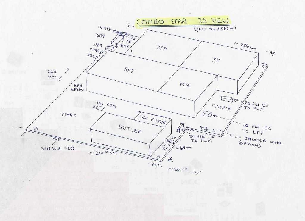
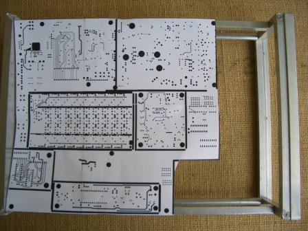
See the PCB concept here. (1.8Mb pdf file) 5th Feb, 2009 (see the actual board overlays below.)
You may need a little imagination though as the groundplane copper has not been poured but the various sections should be plainly visible. Red is top layer, blue is bottom layer.
Below, is a sketch of how the PCB might look. Shielding is with PCB material, or possibly copper or brass strip. Click to enlarge.
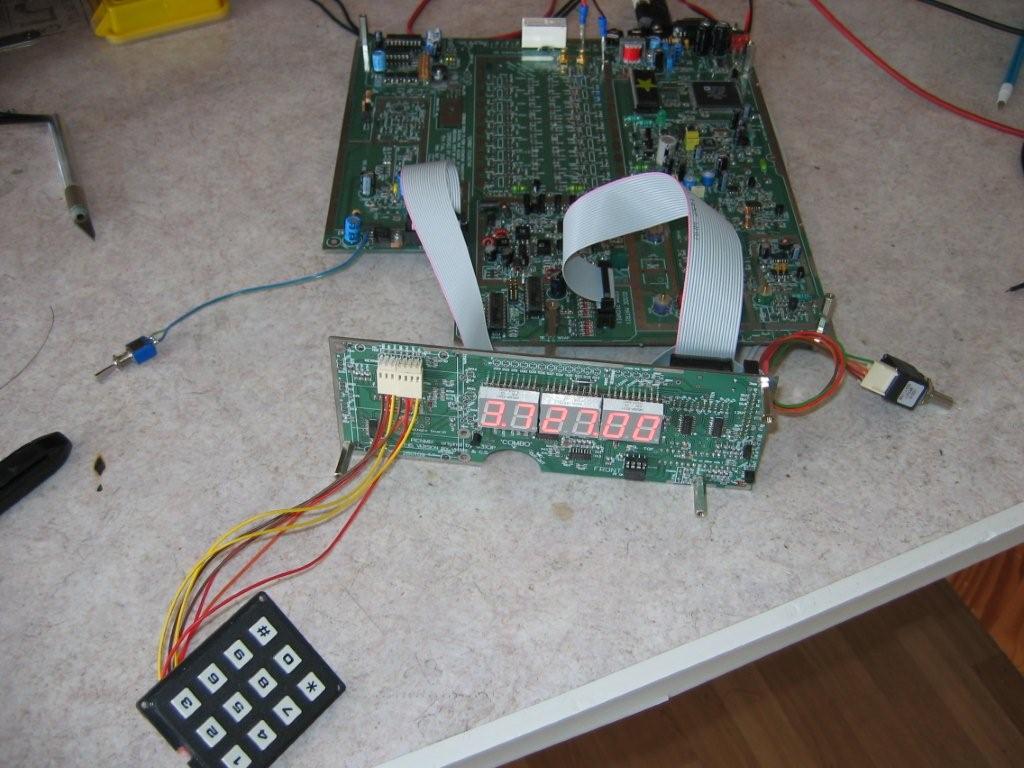
11th Feb, 2009: Below is the actual PCB. There are only a few prototypes made at this stage. Click for larger pictures !


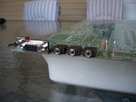
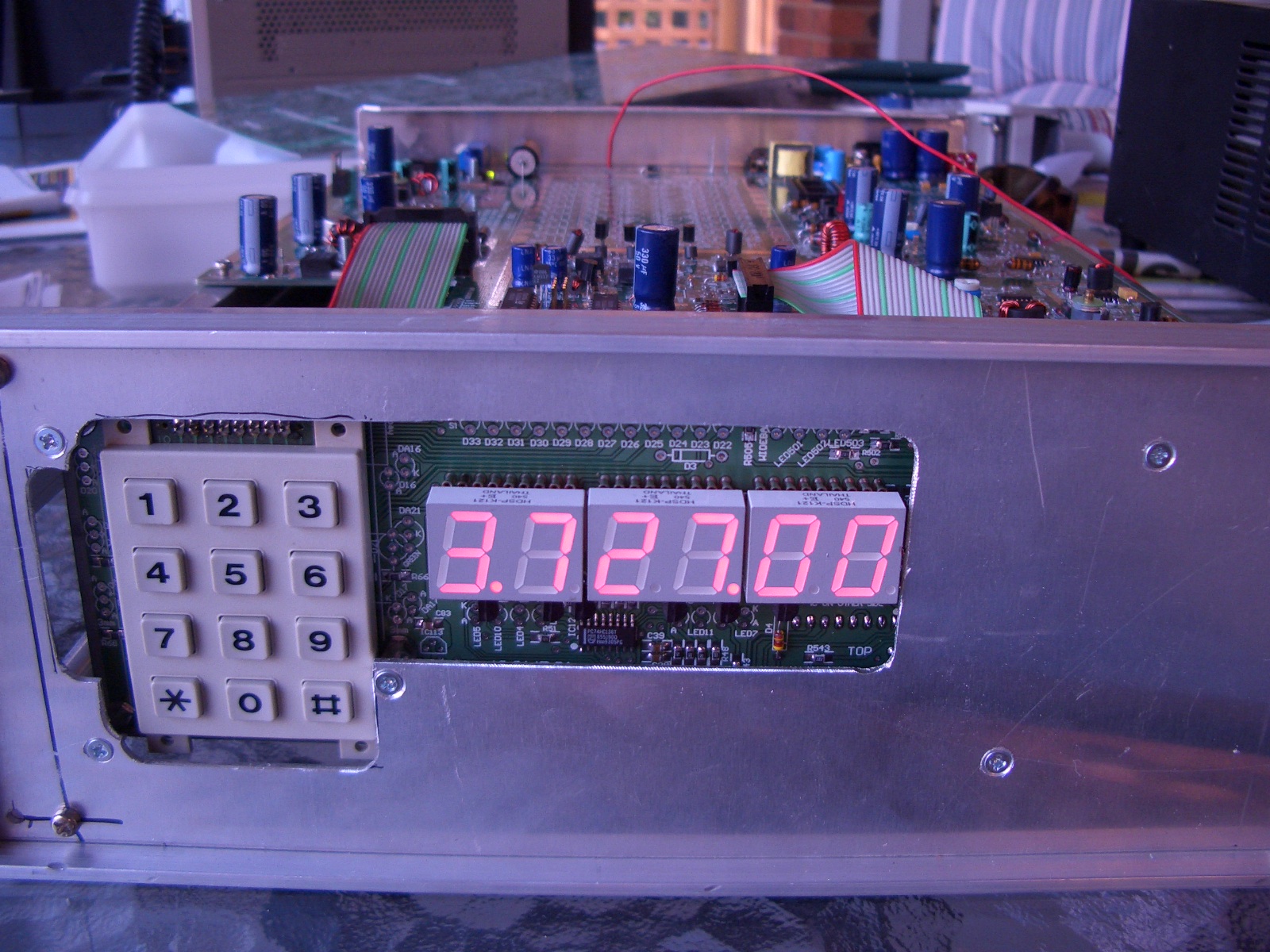
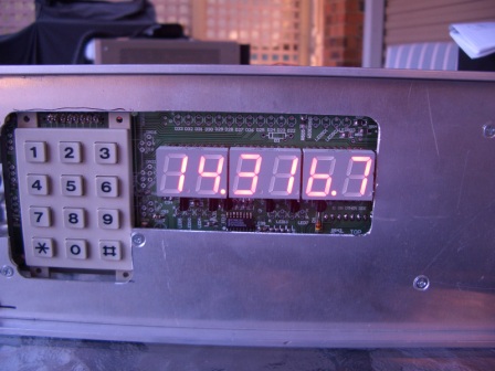
22nd Feb, 2009: Quite a bit of work done to build the PCB. After about 15 hours, this is where I am at. Waiting for some more parts right now, but most completed blocks on the PCB are working. PicnMix shows "3.727" on power up, keypad, Butler Osc, 2nd LO, AF amp. works etc.
Click on most pictures for larger size.

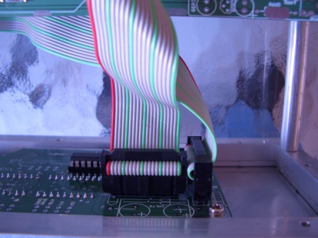
A feature of the PCB is the ease of assembly. Most wiring between the various sections is on the PCB itself. There are a few coax cables under the PCB for interconnecting RF sections. Wiring to the Picnmix (front panel) is via two 20 pin IDC cables, quickly and easily made.
There are some different ways to connect to the Opto Encoder, serial data to Picnmix and the DDS section, which will be explained later. The schematics show some resistors that can be fitted or not fitted to change the path of these signals.
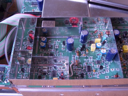
Please NOTE: The BC517's fitted in the MR area in these pictures have been inserted incorrectly. Follow the printed overlay on the PCB when fitting these parts on your own PCB.
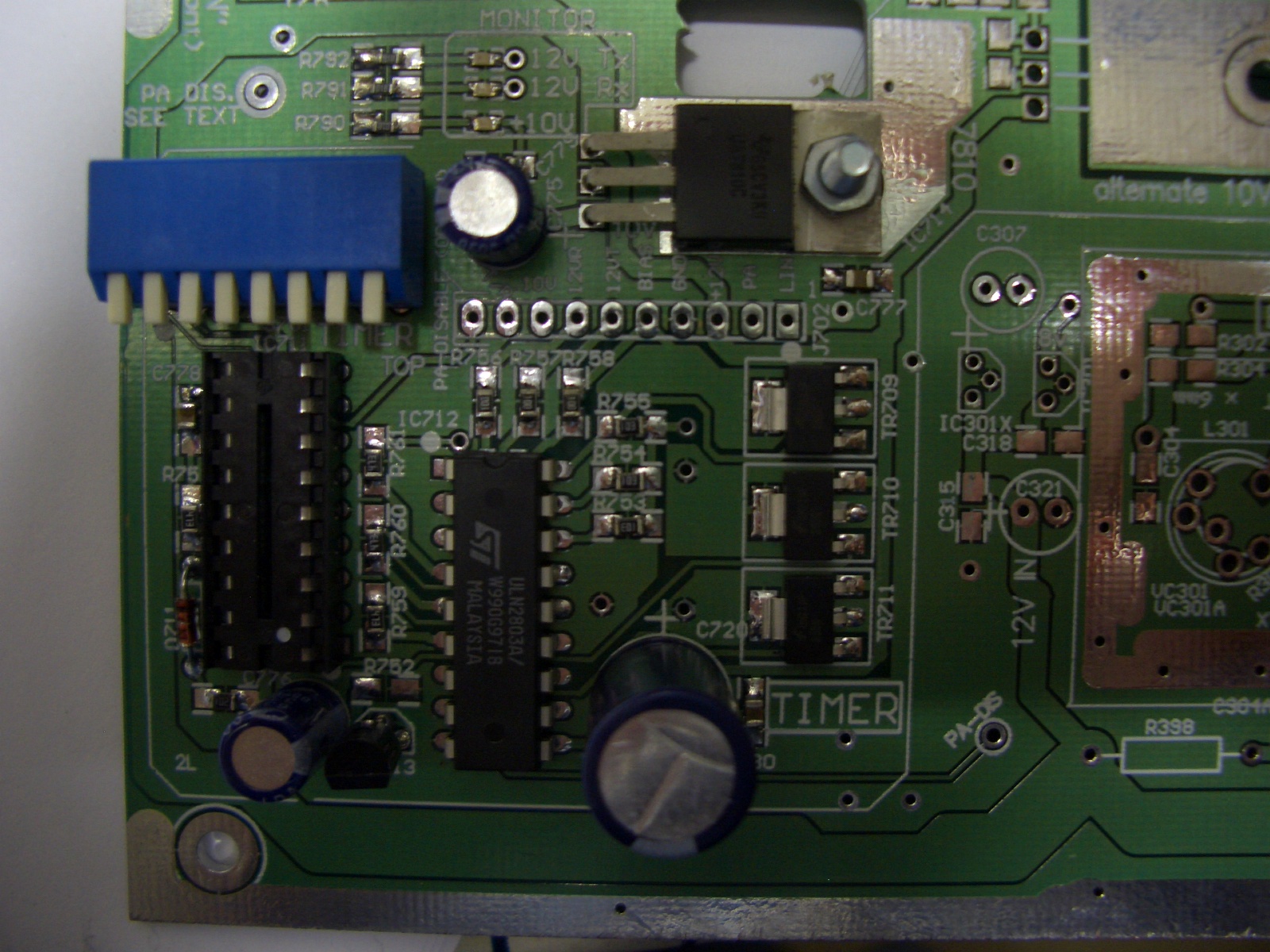
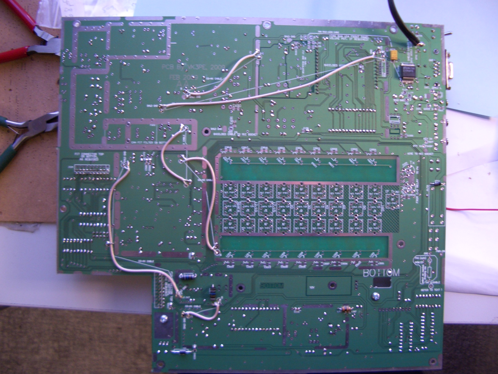
Below: There are some aids to know what is happening on the PCB. eg. a series of SMD LED's show the current band selected. The 10 pin header above the LED's connects to the Low pass Filter.

The front panel is a dummy. It will be behind the eventual front panel and serves only to mount the Picnmix PCB with tapped spacers using countersunk screws. They will be covered by the final panel, giving a neater appearance.
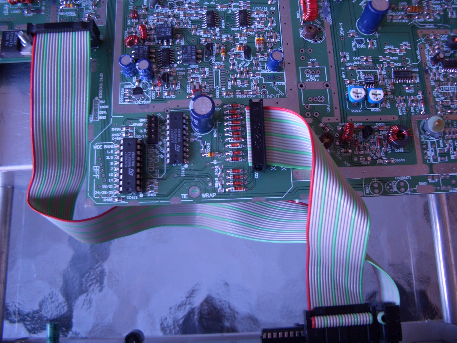
Below: Wiring under the PCB consists of some co-ax cables and audio shielded cable (twin shielded). These cables were then hot-melt glued to the PCB. There are also two short co-ax cables on the top, in the 2nd mixer area. (not shown here)
The cable in the top right of the pictures, is the RS232 (serial) cable to the Picnmix board. I used shielded audio cables.

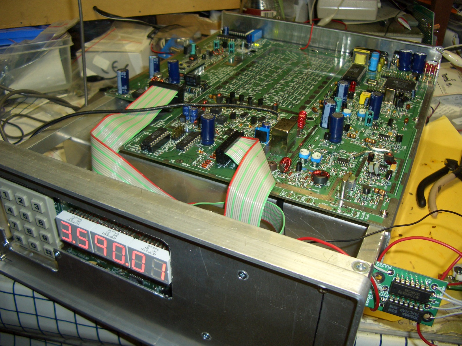
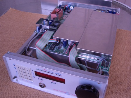
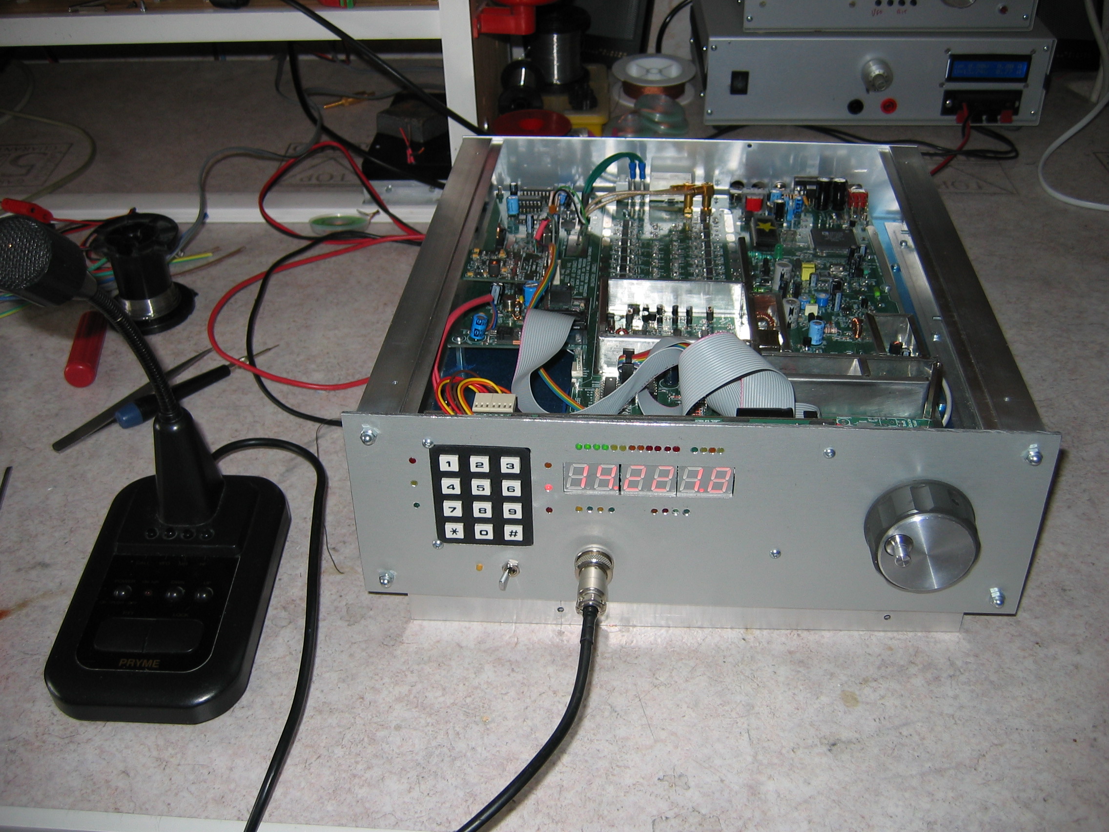
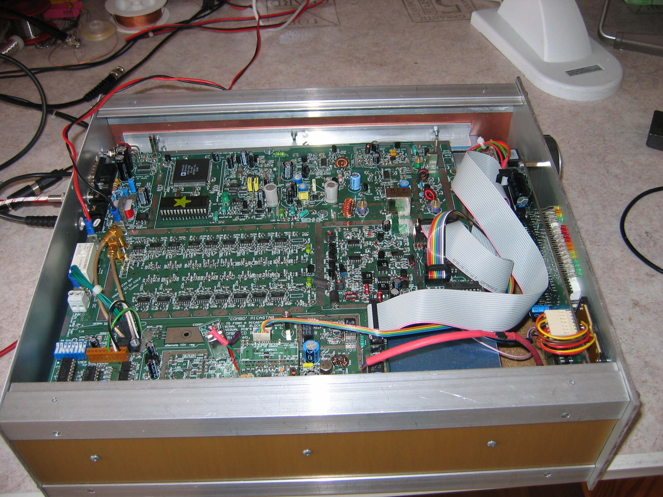
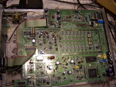 Sorry about the flash! This is the top view of the "finished" ComboSTAR
(on 80M only). In the case, I fitted internal speakers. (one visible top left
of the picture) There is provision to wire them to the switched rear 3.5mm jack.
You will see text on the bottom showing where to connect them to. It is visible
in the picature above showing the audio amp IC.
Sorry about the flash! This is the top view of the "finished" ComboSTAR
(on 80M only). In the case, I fitted internal speakers. (one visible top left
of the picture) There is provision to wire them to the switched rear 3.5mm jack.
You will see text on the bottom showing where to connect them to. It is visible
in the picature above showing the audio amp IC.
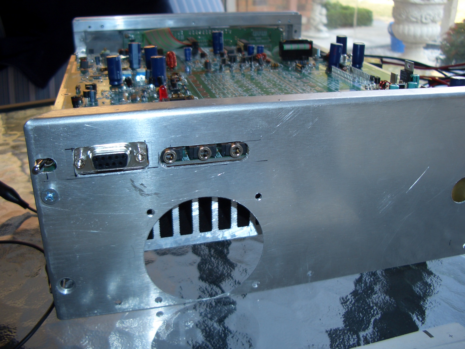
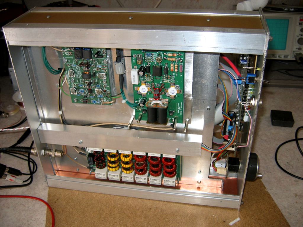
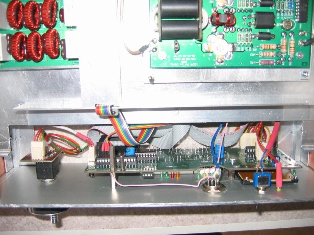
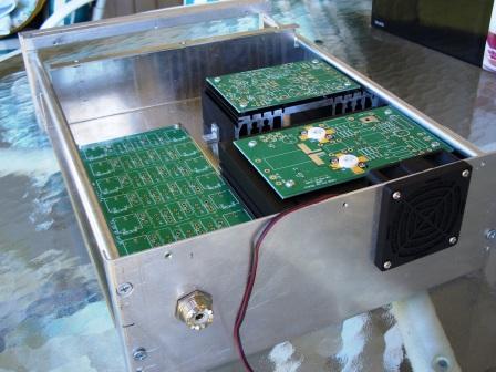
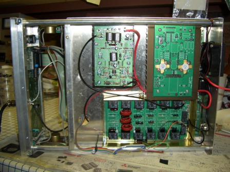 This is a temporary view of the 20W PA fitting. This was just to get on the
air on the 80M net on the 9th March, 2009 for it's maiden QSO. The 140W
PA and the rest of the LPF will be assembled soon and the wiring will be tidied
up! You can also see both loudspeakers internally. I normally use an external
speaker set though but internal is handy sometimes.
This is a temporary view of the 20W PA fitting. This was just to get on the
air on the 80M net on the 9th March, 2009 for it's maiden QSO. The 140W
PA and the rest of the LPF will be assembled soon and the wiring will be tidied
up! You can also see both loudspeakers internally. I normally use an external
speaker set though but internal is handy sometimes.
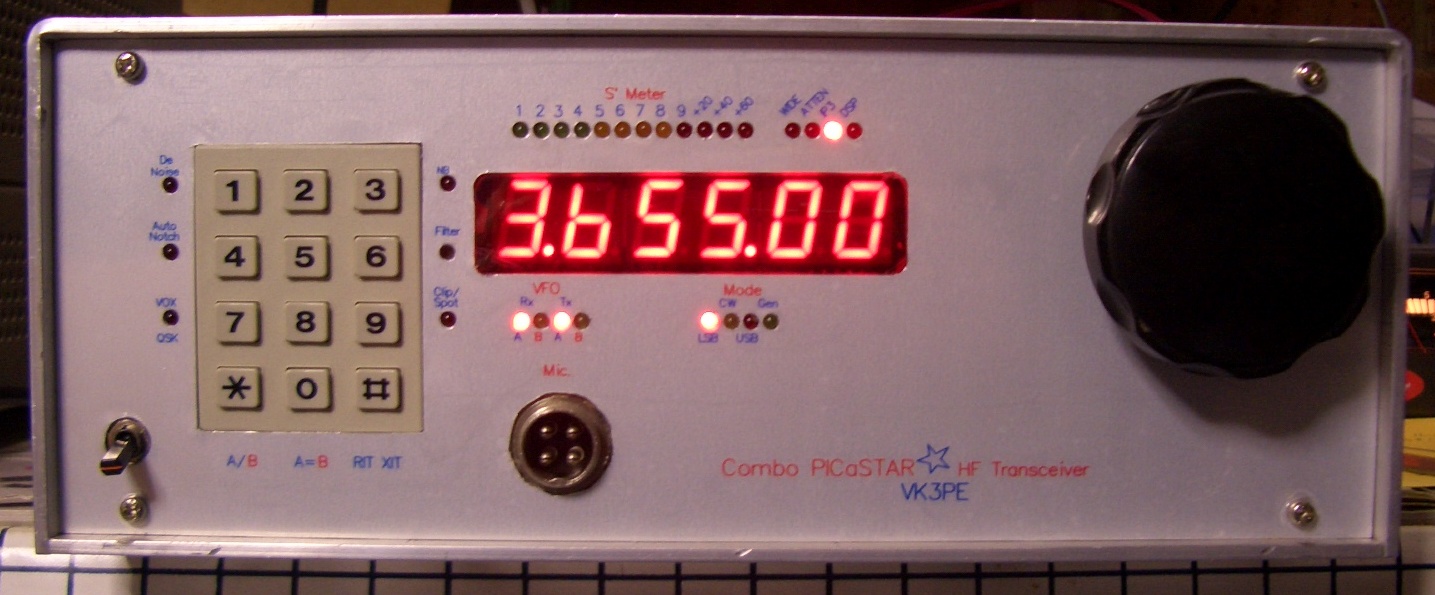
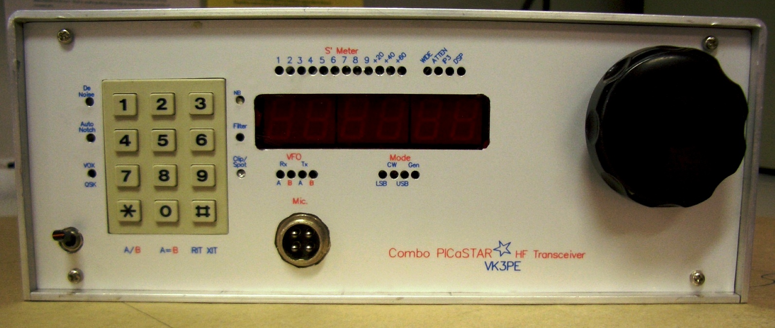
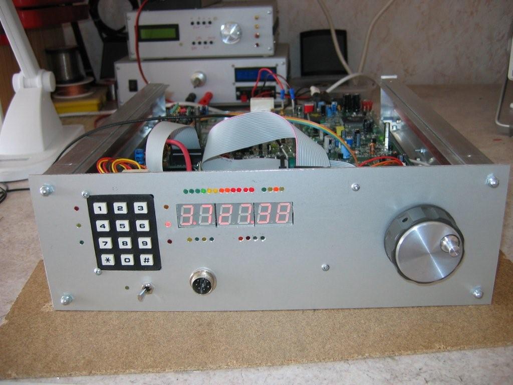
17th March, 2009: Made the front panel. There is a dummy panel under this panel. It does not hold any of the PCB's etc. It just slips over the panel underneath. I made a "lable" using a colour Laser printer onto adhesive backed grey polyester material. I then put a clear protective film over it, like that used on kid's schoolbooks.
 <<-- click to enlarge this image. LED's not yet fitted.
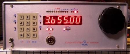 18th March, 2009: LED's now fitted.
SHIELDING
24th March, 2009: Start to fit shielding. I used 0.4mm tin plate bought from RS Components. The DDS section has PCB material for insulation as per the original PICaSTAR design. The shielding in that area is not yet finished. Strips of the tinplate form the walls with the covers having the edge folded over for a tight fit, hopefully RF proof! Click on pictures for a larger view. Underneath, shields will also be fitted.

 Click for larger picture
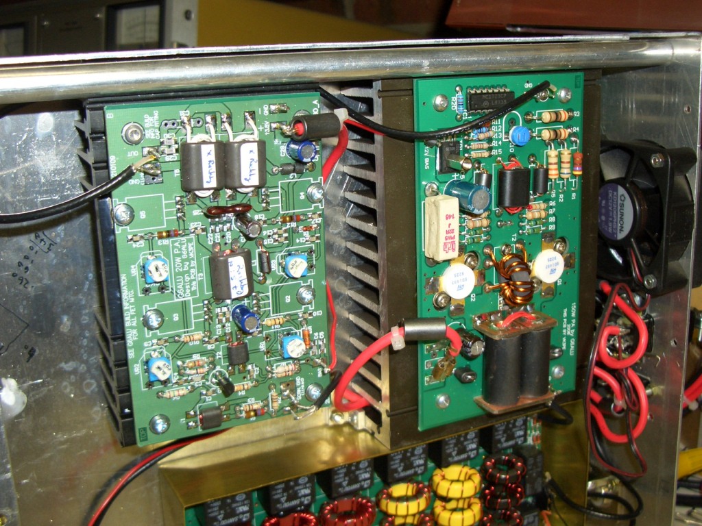
6th April, 2009: 140W PA now fitted and
producing over 145W on 80M. I still need to "tame" it a little as
getting some RF feedback in to the DC cables. It gets pretty hot also! The fan
works ok to cool it, but produces a lot of interference in the receiver.
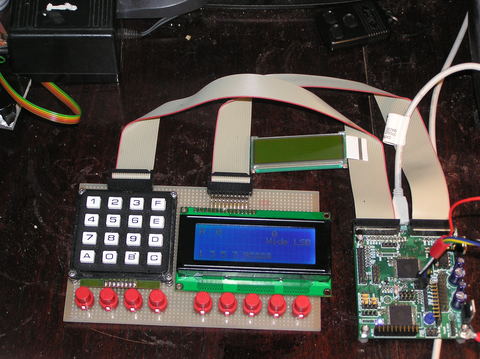
TrxAVR
Alternative controller to Picnmix. This allows a number of different displays to be used, including graphical types.
TrxAVR PCB integration to Combo PICASTAR
The TrxAVR PCB by Ian, G3VPX, (the PCB on the ComboSTAR panel was designed by Chris Stake) is included on this panel of PCB's and provides an alternative display and user interface for the radio with software by Ian, G3VPX.
The display can take several forms, multi line character based LCD modules or full graphics LCD with touch screen.
ComboPICASTAR PCB has been designed to allow the TrxAVR pcb to simply be plugged in, in place of the Picnmix board.
(TrxAVR can ALSO be used on any PICASTAR to replace the Picnmix.)
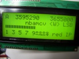
Click here to see my initial interface to a 4 line x 20 characters LCD.
Large graphical displays can also be used !
 Click
pictures for more information.
Click
pictures for more information.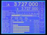
For additional build information, see Ian's web pages on TrxAVR.
You will be amazed at what Ian has achieved.
Note: there is a PCB that can be home built also, on Ian's pages and fitted to ANY Picastar.
I am currently working on a PCB that will incorporate TrxAVR plus keypads and display connections. If you are interested, email me.
Problems found so far in this PCB: (an updated PCB is currently being designed)
MR area: the LM317T overlay is reversed.
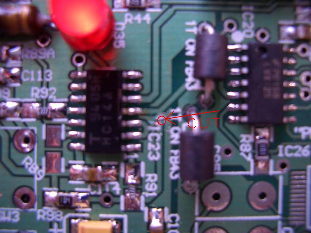
DSP area of IC23 cut the track UNDER the IC23 designator on the PCB. Photo here.
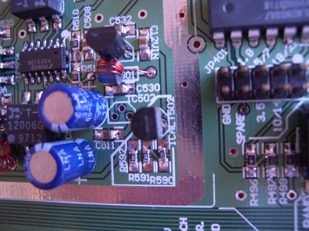
Pin 1 and 5 of the Opto Couplers need to be drilled through. (there is NO hole in the pads) You MUST use a VERY SHARP 0.7mm drill to avoid damage to the PCB. Once drilled, fit the devices. You wll need to trim some pins short and solder to the PCB. Or, you can drill all of the 6 pads out if you wish. When you fit the devices, you will then need to solder both sides of the PCB.
CLARIFICATION
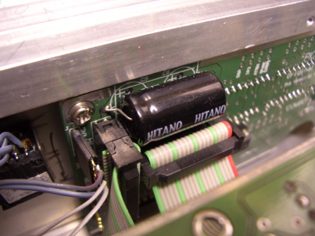
Alternate capacitor fitting on the PICnMIX. You can fit either 2 x 1000uF vertical caps or 1 x 2200uF axial cap. Low ESR types are best.
9th March, 2009: SUGGESTION: This is not an error on the PCB but I found an improvement is easily made to simplify the wiring to the LPF board. If the ComboSTAR goes further, ie a batch is run, then I will change the PCB as follows for this.
It involves a very short link to 12v on the adjacent ULN2803 and a wire from the BPF connector "spare" pin, to the "PA" pin of the Timer.
Full information will be posted here shortly.
Some preliminary ComboSTAR documents.
The Bill of Material (BOM updated 230309, now suffix "_3")
and Schematics
INTEGRATION Drawing updated 23-03-09 (draft)
For the main PCB ONLY.
Parts are essentially the same as that used on the Panels #1 and #2 on other pages here.
ComboSTAR Board, top overlay is here. & bottom overlay
These are 4 sheets each and need to be printed out and stuck together as the PCB is very large. They show the current values of all of the components. The actual PCB shows the reference numbers of the components as per the schematics.
The main PCB has a cutout in one corner. This is intended to accomodate the optical encoder. By mounting the PCB upside down, the encoder will then be on the right hand side of the finished ComboSTAR. In my own metalwork, I have allowed extra depth so the encoder can be mounted with the PCB in the "normal" way.
PICnMIX for ComboSTAR
New 6th March, 2009: PICnMIX PCB BOM, Schematic and Overlay top, bottom
There are two PCB versions supplied with the panel. One has been designed to be a horizontal and thus lower profile. Use the version that suits your planned case.
What is on the Panel?
1) "ComboSTAR" PCB. This is a (large) single board version of a PICaSTAR without Picnmix or LPF stages. The schematics are for this section only.
2) 20W PA board by G6ALU. Identical to that used before. See G6ALU web pages and my build here.
3) Picnmix by VK3PE. This is the "front panel" board similar to the previous panels, but slightly shorter. Connections are now made to the main PCB with ribbon cables. See link above for build onfo.
4) DDS carrier. 2 types, one identical to the previous versions and also by G3XJP. The 2nd is a horizontal style version, to allow a lower profile. Only ONE board should be built though.
5) An alternate footprint
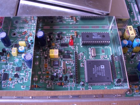
sub (plug-in) PCB for the ADSP-2181. Overlay
here.(800KB) This is normally NOT used as the main PCB has the DSP on it.
Used only for alternate footprint DSP chip. Do NOT
use this PCB
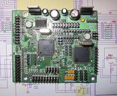
6) TrxAVR board. An alternate 4 x 20 LCD or Graphics controller to the Picnmix board.
More Details in link above or here.
This PCB can control the Combo STAR and use either a graphics display or a 4 x 20 LCD module. This is preliminary but shown below are pictures of the prototype development by Ian, G3VPX and Chris S.
Click pictures below for larger size.
Michel, F1CHM, is also building this panel as a "pioneer".
2nd April, 2009 Michel reports part built and working so far. {click for larger picture}
Update 9th April, 2009. Michel sent some more pictures and says Receiver is working and Transmitter ready for initial testing. BPF Toko's about to be wound also. < click for larger pictures also >

21st April, 2009. Michel has now wound all of the Toko BPF coils and assembled the PA's and LPF. In fact, it appears the radio is now finished and Michel advises he will start testing in 2 days time. We look forward to seeing this one on the air.
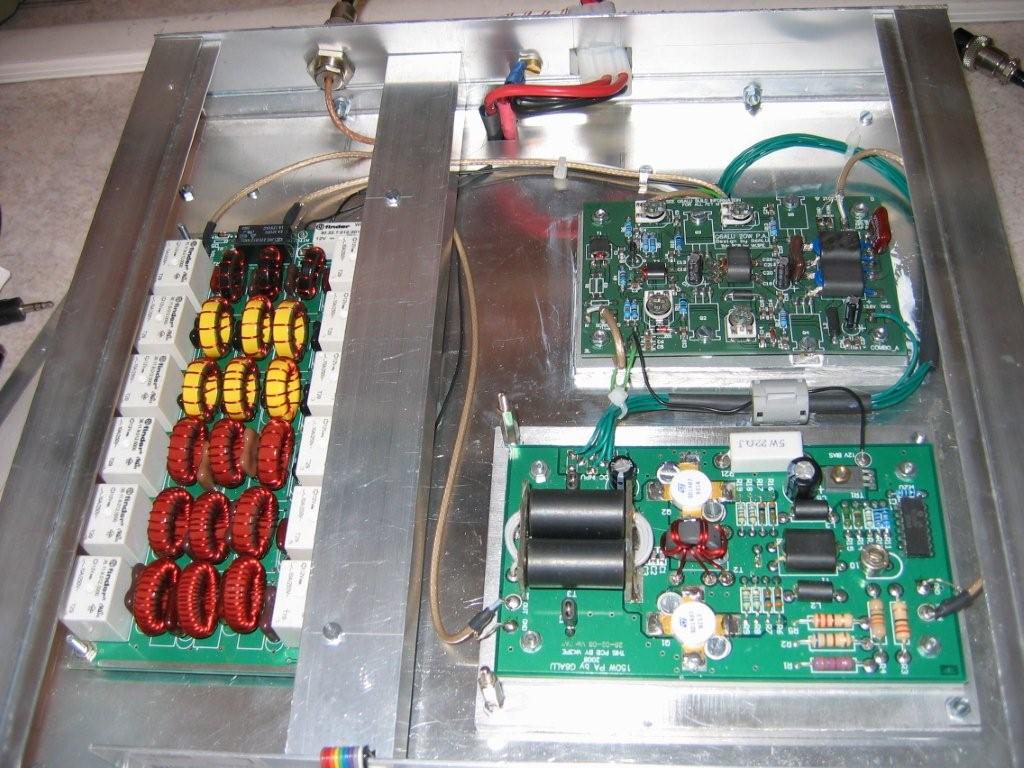
These pictures emphasise the small amount of wiring required in building a "ComboSTAR". The wiring is simplified as many of the connections are tracks on the PCB and interconnection to PICNMIX uses ribbon cables.
{click for larger pictures} For super large pictures below, click here and here. I appears that Michel is using other than the Butler for the ref. oscillator as there is a small PCB in it's place.

5th May, 2009: Michel, F1CHM, reports that his Combo PICASTAR is working on all bands after an initial QSO on 80M. Michel also reports that he has switching to allow either 20W, 140W or -10dBm output for a transverter.
Shielding walls have been mostly fitted if you view the large image below by clicking on it. (then click again for even larger)
Well Done Michel! (click for larger image)
Ready for a QSO !
View of the PnM on front panel, from underneath.
Neat and clean underside view of PA area.
The other Combo PICaSTAR builders.
Bill, VK7MX, is progressing well as time permits. No pictures yet.
Johan, DK1CS, I don't know progress of Johann's PCB.
Eric, VK3AX, will start mid year.
What is NOT on the Panel?
1) 140W PA by G6ALU
2) Low pass Filter by G4TZR
A separate panel containing these two boards might be looked at later if any interest.
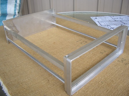
See my PICaSTAR mechanical concept below:-
This is how I did it, yours will obviously be different.
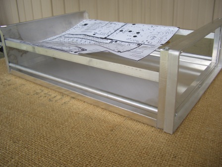
OK, to see if this might work, I made a case from standard aluminium extrusions, screwed together. The length is a little long here as the thinking is to eventually reduce it to suit the final PCB if it happens. Its easy to do, by shortening the side rails and re-tapping them. The side rails are held together with 4mm machine screws, mostly countersunk head type.
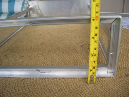
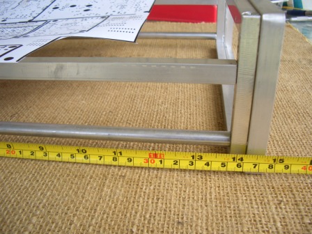
Case is about 260mm wide by 100mm high and currently 360mm deep. Side bars are 12x10mm square bar and 10mm rod. Front is backed by 12x10mm bar and a lip is formed around the front, for the front panel to sit into, with 12x12 x3mm angle. All are tapped and screwed together. Fiddly, yes, but achieves quite a nice result.
Bottom is 1.2mm sheet aluminium with 10mm edges turned up and top will be an inverted "U" that fastens into the bottom and also the front and rear panels.
The PCB sits on top of the square bars and components/shielding height will be just be just below the top cover level. The Toko coils will protrude below the PCB, but be about level with the bottom of the bar. That leaves about 60mm for other "stuff". eg the PA's and LPF will be packaged on the bottom. See pictures below.
(there is some distortion due to the camera) Dimensions are shown for interest only and are of MY CASE.
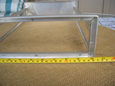 Dimensions are shown for interest and are of MY
CASE.
Dimensions are shown for interest and are of MY
CASE.
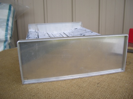
Front panel inserted. It will be held by 4 screws, tapped into the frame. There will also be a panel behind it, to fasten the PnM etc to with countersunk screws.. That then allows the "cover" panel to be fitted with only 4 screws in the corners for a "nicer" look. ie. no ugly screws.
There is about 60mm underneath, for inclusion of the PA's and LPF boards, with a 60mm fan. The LPF will have a shield fitted to it. The PA's etc fit onto a sub chassis, with a 60mm folded section at the front of the case. Still to be fitted are a fuse holder and DC power input connector.
The bottom cover has a 10mm lip on three sides. Rear lip fastens to the rear panel. Top cover fits over and will fasten to the lip also. I will be using tapped inserts or riv-nuts for that job.
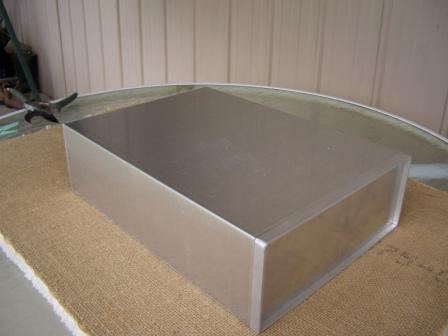
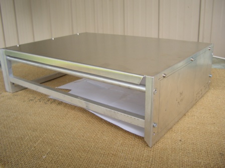
This is the top cover made from 1.2mm aluminium. It will be fastened to the bottom and front/rear, using 3mm screws.
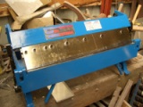 I have this 600mm wide capacity Panbrake of Chinese origin for bending the covers.
Covers are 1.2mm aluminium. Lacking a folder like this, similar results can
be achieved using flat sheet with light gauge angle aluminium extrusion for
the corners.
I have this 600mm wide capacity Panbrake of Chinese origin for bending the covers.
Covers are 1.2mm aluminium. Lacking a folder like this, similar results can
be achieved using flat sheet with light gauge angle aluminium extrusion for
the corners.
I use a jig saw mounted upside down, to cut the aluminium sheets. If you do this, take extreme care of your FINGERS and wear eye protection. I am not endorsing any method of making the mechanics. It is presented for amusement only.
BACK to my PICASTAR information.
Visitor
From 20th March, 2009.
Created on 28th Nov, 2008.