 Panel #1
Glenn PCB's for STAR
Sept 2020 minor changes only.
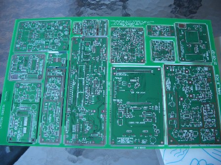
This page is for the '1st' panel. (late 2007,early 2008)
It has all of the PCB's for a PICaSTAR except the BPF board.
Page last updated on September 1, 2020 { Rockby parts sold out}
Codec page updated for version "B" CODEC PCB (panel #2)
Oct 2, 2008 new BOM
22nd Sept, 2008, Note re resistor values on PnM board
The original PICaSTAR documents do not include a Power amplifier or Low pass filter
Panel #2 Has a 150W PA & a LPF plus other boards. (Panel #1 has a 20W PA)
Panel #1
Bill of Materials (BOM)
Please note that all the PCB's on Panel #1 are combined into one document. The document is for these PCB's only and may not include all parts to build a STAR.
BOM for LPF & BPF are NOT included, for example. ie. the "BPF Panel #2 is not included. See Panel #2 page.
BOM for all Panel #1 PCB's (Excel) UPDATED 3rd Aug, 2009 (_15)
18th May, 2008.
Please note that the transformer T1 on IF schematic is shown as
"L2" on the BOM for the IF Board. This error will be fixed soon.
BOM's for Panel #2 ........ refer to panel 2 page please.
For VK builders:-this might interest you, I found that Rockbies have: (subject to your own verification!)
1) the ferrite beads ! There's a bucket load of them in a STAR build as you know. p/n 33026 is type FB43-101 same type i bought from TTS systems for 30c each. (and they have run out of them) Rockbies are 20c. min QTY = 10, and they have 6430 of them !!!!
2) SOLD OUT ! also, the "tubes"used in the output xfmr of the 140W PA...... spec is 43-0402 type from RS components #467-2750 (fairite number is 26435540402) $2.08 + GST min qty = 5 from Rockby #12190, 298 in stock at $1.70 each. Just slightly different size but maybe rounding errors when they measured it. Two are used in the PA.
BOM for all Panel #1 PCB's in PDF format (_11) still at 5th Nov for now.
NOTE: diodes on the IF board shown as BA224, should be BA244. However, 1N4148's will work also at a pinch.
8th Nov: TLC7524CD is listed as TLC7524VD which is incorrect.
25th Nov DSP Motherboard, Change R90 to 3k3 (3.3k)
Jan 9th, 2007. Please note that any reference to an actual frequency, for the Butler oscillator, is an example only. You can use a variety of frequencies depending on what you have available. Refer to original STAR documentation.
Feedthrough Capacitors: try http://www.danssmallpartsandkits.net/index.html
About half way down the page are 1nF 400V F/T caps made by Stettnor. These are the ones I am using although, I got mine off Ebay. Check this vendors Postal charges though, they are quite high.
28th July, 2008. In VK, subject to actual confirmation of size, WES Components (Sydney) have 1nF/50V #FT318-1000
I have not seen or measured the parts to see if they will fit the IF board etc so it's up to buyers to check first if they fit the 3mm D holes in IF.
NEW 28th Jan, 2009 CRYSTAL FILTERS
Suitable filters can be found in various CB radios. Typically marked as "10M4D" or similar.
eg AX144 , super lion2 , super tomcat 2, cobra 148 and Uniden PC-122
Many thanks to Nick, VK3UCK, for this info.
Panel #1, PCB Updates & Corrections:-
CODEC
the 1uF caps do not have polarity marked. See the link below.
31-10-07 The footprint on the PCB is INCORRECT for an LM317 (alternate part to LE33CZ) See CODEC link for information.
PICnMIX display board.
The 6 x BC327's are shown on the PCB reversed. See link below for picture of correct insertion.
Line here removed 210708. See 9th jan below instead.
31st Oct -07 It's preferable to use the DIP version of the 24LC256 eeprom as it appears the SMD part is too wide. If you get the SMD part though, it is possible to fit it by scraping some of the resist off, near the edge of the PCB, to solder the 4 pins on that side. They are all ground.
The text near JK1 shown as "15MHz" should be "5MHz".
5th Nov. G4IZS has identified two potential ground problems on the display board. See PICnMIX page for details.
26th NOV Butler heater transistor should be TIP122, not TIP123. Schematic updated, see link below.
9th Jan 2007 Viv has identified an over dissipation problem in R19. This resistor feeds the 7805 regulator and may overheat. It is best replaced with a 1W axial 10R resistor fitted from the through hole near C2 across to the input pin of the 7805. (near C16) The existing R19 should be removed. More details with picture in the PnM link below.
31st Jan 2008, Note that the S'meter will read in reverse. (Msg #28145 & 28146) ie. Right to Left. This is easily fixed by loading the correct version of the STATUS board code into the 16F627 Status PIC. Peter has added new source code for this PIC, which can be assembled for Glenn pcb's. ie. correct the readings. No changes to the PCB are required.
7th Jan 08 R73a on component overlay is shown as 1k, SHOULD be 4k7 as per schematic and BOM
22nd Sept, 08 The three resistors feeding the ATTEN, IP3 and DSP LED's are shown as 3k3. You may elect to reduce them to 1k for better brightness.
PICnMIX, Butler board
8th April, 2008. My schematic shows the 2N3866 output transformer as L100. In Peter's original, this is T1.
Matrix/AF Amp
It is better to trim the audio IC pins back a little before soldering it on. See link below.
It appears the LM4940TS audio IC may a little hard to get for non-VK's now so I suggest you buy yours as soon as possible.
31-10-07 However, the LM4950TS should also be ok and is available from Farnell.
06-12-07 There's a mix-up in the labelling of JP503 pinout for the LPF. Details below. (affects integration also)
02-03-08 A problem found by Paul, the resistors have no ground even though the PCB package says they do! Connect one of the resistors (R506)to gnd with a wire to JK501-10 or drill a small hole thru the PCB at the R506 gnd point, insert and solder a wire to both sides.(scrape resist off first)
DSP Motherboard
31-10-07 The MAX232/ST232 should be the wide type. eg MAX232EWE or MAX232CWE
23-11-07 The value of R90 is too low to allow the next stage to drive the front panel DSP LED. Change R90 to 3k3 (3.3k)
MR Board
22-11-07 correction to overlay.
22rd Dec 2007 Schematic and overlay corrected:- U310 changed to J310 in 4 places See below.
26th June, 2007 Jay Cox has found a missing ground. See MR link below for details.
IF Board
23rd Dec 2007 Minor update to schematics, does not affect build or BOM.
Integration drawings
Ver 8: PA wiring is NOT proven, use with caution !
PANEL #1
Links to Integration, front panel drawings etc.
ATTENTION !
(disclaimer)
The information on these pages is of a general nature and is provided in good faith, but no guarantees are made of it's accuracy or completeness.
Drawings and information are provided in good faith and is intended to indicate one possible way of interconnecting a range of modules to make a transceiver. It is not a substitute for experience or may not represent good construction practice, mechanical layout or assembly of this project. The selection of parts, wire sizes, enclosures, shielding, location of PCB's, grounding points, de-coupling, etc. are up to the individual constructor.
This project is NOT a KIT !
INTEGRATION (how to put it together !)
Integration drawing Ver 8 19th May: Update showing 150W PA, LPF and BPF. PA wiring is NOT proven, use with caution !
Four sheet version (~1.2Mb pdf)18th June, 08. Contains enlarged version in 4 pages.
Integration Drawing in 4 sheets so you can make a bigger sheet.
MECHANICAL (where to put holes)
Front panel drilling for mounting holes and LED drilling 6th Nov
NEW 23rd Nov A fully dimensioned colour drawing also for front panel drilling. Thanks Chris S.
Note: you do not have to drill all the mounting holes shown. For my STAR, I used the holes marked A, D, F, J & H
Links to individual PCB documentation.
Component overlays, pictures etc for the STAR panel. (NOT the BPF Panel {panel #2} )
PCB Hints & kinks updated on 13th Jan 2009
Buzzer/Beeper PCB Updated Oct 2009
Build this to check your work. It is invaluable.
PICnMIX Display and Butler PCB's
NOTE! the BC327's (6) on the display board should be inserted opposite to that printed on the PCB overlay !
(this is corrected on the bonus "B" version on the BPF panel, Panel #2)
ERROR GND corrections added Panel #1 only 5th Nov
ERROR ! 9th Jan 2007 Viv has identified an over dissipation problem in R19. See link above for details.
(this is corrected on the bonus "B" version on the BPF panel)
31st Jan 2008, Note that the S'meter will read in reverse. (Msg #28145 & 28146) ie. Right to Left.
This is easily fixed by loading the correct version of the STATUS board code into the 16F627 Status PIC. Peter has added new source code for this PIC, which can be assembled for Glenn pcb's. ie. correct the readings. No changes to the PCB are required.
7th Jan 08 R73a on component overlay is shown as 1k, SHOULD be 4k7 as per schematic and BOM
NEW Pictures and information of the R11 & R12 holes added 3rd Dec 2007
26th June, 2007 Jay Cox has found a missing ground. See MR link above for details.
NOTE: G3XJP's Official Mods: Ver 19:-
IF board * Variable 22k resistor in IC6b output to C18 (net Rx gain trim).
Values lower than ~100 ohms may produce LF instability in IC6b (perhaps only on T/R/T transitions).
Observe with 'scope on C18. 1) Remove C61 and R7 and then 2) if you *have* to find more gain to meet spec (during IF Cal) , reduce pad (82R/100R/82R) before Tr3. Suggested values 470R / 100R / 82R.
4th April, 2008: Overlay clarified for fitting of Mixer transformer
Feedthrough Capacitors:- see link above for a source. 7th Nov
DSP Block is working (initial test) . See the VIDEO ! 1st Nov 2007
8th Nov, 2008 Version "B" information added.
Correction to fitting of IC24A ! 31st Oct
(this is corrected on the bonus "B" version on the BPF panel)
The version "B" on Panel #2 is the PREFERED board to use as the footprint for the CODEC and regulators have been corrected.
DSP block assembled with VIDEO !
DSP Mother board plus CODEC and DSP boards
Diode Matrix & Stereo Audio Amp (based on G6ALU design)
16-06-08 Minor correction to pin name of AF amp IC. (schematic)
02-03-08 A problem found by Paul, the resistors have no ground even though the PCB package says they do! Connect one of the resistors (R506)to gnd with a wire to JK501-10 or drill a small hole thru the PCB at the R506 gnd point, insert and solder a wire to both sides.(scrape resist off first)
06-12-07 There's a mix-up in the labelling of JP503 pinout for the LPF. Details in link above.
G6ALU 20Watt Power Amplifier Link (full build information and set-up for PICaSTAR).
Pictures of VK3PE build of this PA
Testing of my PA. Some initial results. 18th Dec 2007
Last updated on: September 1, 2020
16th October, 2007. This page originally created.