IF Board
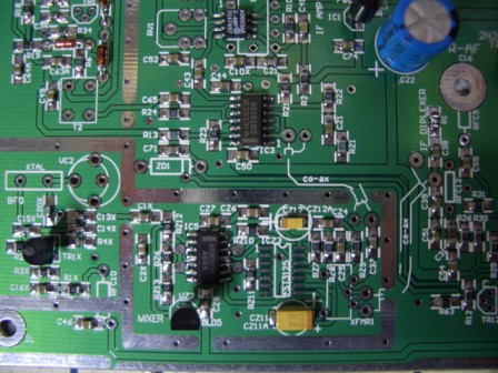
Most parts loaded as you can see, with no problems. The two SMD electro capacitors (yellow in left picture) have a dual footprint allowing a leaded part to be fitted instead.
Also, note that either a DIP or SMD AD603 IC can be fitted. SMD used in this build. (Upper centre of left picture). You can also see the style of trim-pot used, in the pictures.
4th Nov. Diodes on the IF board shown as BA224, should be BA244. However, 1N4148's will work also at a pinch.
23rd Dec 2007, minor schematic update. Removed ref to co-ax for 10.710MHz Osc output, sheet2.
Please Note: Any inductor or transformer details shown, are for a 10M4D type filter, per G6ALU. If you use a different filter, you may need to modify these parts to match the filter.
4th April, 2008: Overlay clarified for fitting of Mixer transformer
PCB overlays (old drawing for ref only)
and Schematic:-
Updated 020908 to show mods around TR3 here
Old version for Ref only ! Sheet 1 & Sheet 2 here
NOTE: Official Mods: Ver 19:- IF board * Variable 22k resistor in IC6b output to C18 (net Rx gain trim). Values lower than ~100 ohms may produce LF instability in IC6b (perhaps only on T/R/T transitions). Observe with 'scope on C18. 1) Remove C61 and R7 and then 2) if you *have* to find more gain to meet spec (during IF Cal) , reduce pad (82R/100R/82R) before Tr3. Suggested values 470R / 100R / 82R.
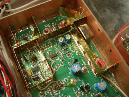
180808, NOTE: In the schematic (sheet 1) it may not be clear around the 10.715MHz oscillator section that RFC10 connects to a feedthrough capacitor, mounted in the shielding around the oscillator section. The end of the f/t cap out side of the shield, connects to the 10v point on the PCB. The capacitor is visible in the 2nd set of pictures below.
Shielding, I used copper but I believe brass or even an old tin plate coffeee can etc could be used.
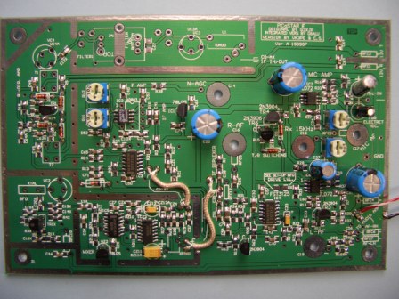
Dec, 2007: My IF board is now finished and is running in my "completed" STAR in Rx mode. Shield covers yet to be fitted..
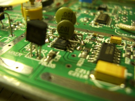
Picture below left, shows the mounting of the leaded capacitors over the mixer section of the PCB.
NOTE:- The crystal filter may be mounted on either side of these PCB's.
Peter's original boards have it fitted on the bottom and that is the suggested mounting side. There is an area around the filter to fit shielding on both sides of the PCB in the Filter area and this should be done also.
I elected to fit the filter on the top.
Either the 10M4D or ITT type filters can be fitted directly onto this board.
Be careful mounting the filter as it is easy to introduce a short on the input or output pin of the filter.
VK3PE
September 2, 2008