Magic Roundabout
Last updated October 13, 2009 (transformer pin-out)
MR component overlay Now "Update-2" version (see below)
ERROR ! Overlay showed CSQ1 & CSQ2 as 2k2. Should be 1nF caps. Overlay document is now :Update-1" version 22nd Nov 07 (Thanks Paul)
Schematic and overlay corrected:- U310 changed to J310 in 4 places Now version "2" 22rd Dec 2007
26th June, 2007 Jay Cox has found a missing ground. See below for details.
CAUTION ! If you use commercial transformers, ensure the orientation is correct, before soldering to the PCB. ie. do not assume that pin "one" on this pcb, is correct for the transformer you may use. If in doubt, refer to the Data Sheet for the transformer. (14th Feb 08)
eg. For some weird reason, Minicircuits marks with a dot not the first pin, but the last one (pin 6).
The pin numbers on my schematics for transformers T3, T4 and T5 may NOT reflect the pin numbering on any commercial transformers. Check the data sheet for the parts you have and compare with the actual PCB.
RS Components have the ferrites for the Baluns, part # 212-0594 (In VK, must be bought in 5's @ $1.23 +GST each)
MR Schematic Includes "pad" modifications.
The MR pictures below are from my previous STAR, which is slightly different.
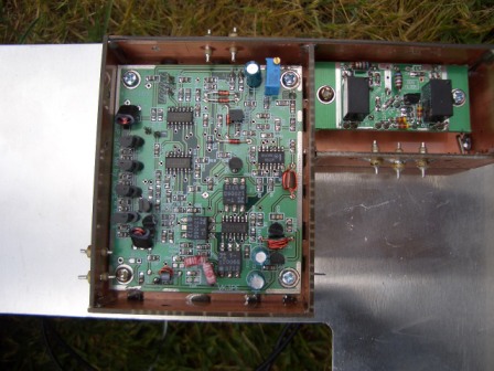
This is the MR from my previous STAR build. I have made a PCB enclosure which contains the MR and DDS filter boards. A coax cable will pass from the DDS filter through the pcb walls to the MR. Each PCB is mounted on tapped 10mm high pillars (spacers).
Later, when wiring is finished, covers will be fitted to complete the shielding.
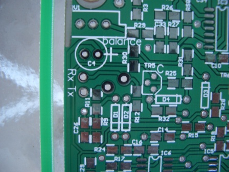
NOTE: The MR PCB supplied on the Panel, has provision for mounting of R11 & R12 through the PCB as per original design. There are large pads next to these resistors which you will need to drill out to clear an SMD resistor, then fit the resistors through the holes. Place a short wire link or 0R resistor across the original pads. Refer to the original documents on the Yahoo group, for details.
This picture shows the location of the holes to be drilled (centre of picture) to follow peter's original design. This is the reccomended method, but you may do as you wish, of course. If you decide to drill them out, use a series of drill sizes to open up the hole slowly, to avoid possible damge to the PCB. Of course, the hole needs to suit the size of resistor you are using for R11 & R12.
I elected to pass the wires from R11 and R12 to 1nF feedthrough capacitors on the PCB enclosure,as you can see at the top. This is NOT an approved modification.
CAUTION:-
If testing this module on it's own, make sure you fit an isolating capacitor on the RF in/out port or you will damage the FST device !
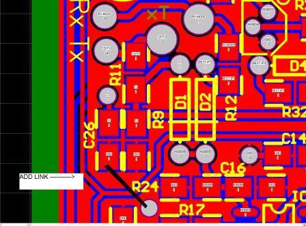
26th June, 2007 Jay Cox has found a missing ground. Again, my PCB program has failed to find a problem when doing the error check. There is a ground missing from the bottom of C26 and R9
Thanks, Jay, for finding this problem. It does not seem to affect the operation of the MR but should be corrected on your boards. Easiest way I can see is to add a short wire link from C26 to the ground Via just below R24 text. See black line in picture below.