DDS Carrier for PICASTAR
Last updated on November 13, 2008 Files information location has changed.
DDS
Carrier This
link is to the PICaSTAR Files section.
Files for the DDS are now in the picaproject group on Yahoo, since the PICASTAR group was shut down. You must be a member to access the files.
The link is Peter's build information for the PCB. Print it out and follow it for construction and test. It is recommenced that you "beep" the PCB as per the instructions to ensure an error free build. Once the AD9951 is soldered down, it will be very difficult to remove it !
There will be some points that may not apply to this PCB build due to plated through holes etc. but they should be obvious.
4th Nov Here are my own files for this PCB. Schematic & Component Overlay
NOTE: although the PCB overlay shows FB on the bottom, it should be fitted to the top of the lower PCB to avoid possible conflict with the 28 pin socket on the Butler board. See the picture on this page. (Thanks Jay)
The PCB supplied on the panel is near identical. There are some assembly differences, which are shown below in the pictures.
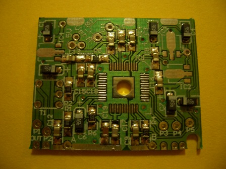
Partially built DDS Carrier. Note that IC2 on this PCB mounts normally on the PCB. It is NOT fitted vertically as in the G3XJP file above.
All holes, including the hole under the AD9951 (centre) are plated through.
![]() This is
how the output transformer is fitted. It MUST be mounted on a slight angle
to avoid any shorts to the adjacent components.
This is
how the output transformer is fitted. It MUST be mounted on a slight angle
to avoid any shorts to the adjacent components.
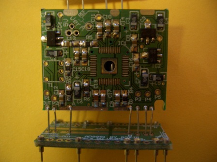
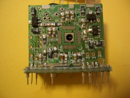
Below are some more build pictures. The last thing I will mount is the AD9951, after I check the voltages when the PCB is powered up.

11th Nov 2007:-
Here is the DDS Carrier finished. It has been inserted into the PICnMIX Butler board and is working fine ! See the PICnMIX link for details.
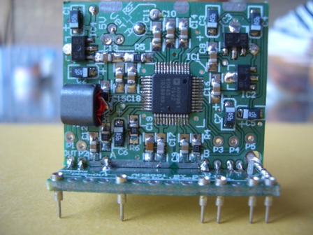
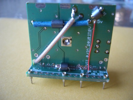
Note Ferrite bead is on top of the base board. (above right picture)
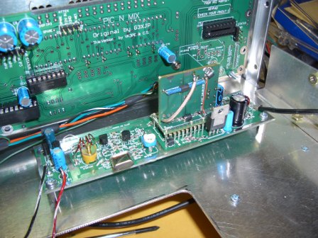
Temporary wiring only here. Crystal (25MHz) yet to be finally fitted and PCB housing for the Butler to be made and fitted. The DDS Filter board is on the other side of the chassis to the right. A hole has to be drilled in the chassis to pass the co-ax cable through. The 5v regulator for the DDS will need a small heatsink.
The large hole in the chassis is for the DSP & IF section.
A hint for building this (and other small PCB's)
I use a small hobby bench vise to hold the PCB while I solder parts to it.
November 13, 2008