Glenn PCB's for STAR
Last updated on September 1, 2020 References to Picaproject now not valid.
G3XJP closed down the Picaproject group and removed all files therein. Reference to these files in this page are no longer valid.
October 13th 2008 (tidy only)
"Panel #2"
This page is for the 2nd PCB panel for PICaSTAR builders.
It has the Receiver BPF that is part of PICaSTAR plus some other non-STAR boards.
Page under construction!
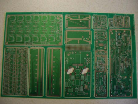
This PCB panel was made and shipped in April, 2008.
This panel contains the BPF plus Steve's 150W PA and Ray's LPF PCB's.
Plus some "bonus" PCB's (see below) to fill the space and make it more economic.
Errors, problems, etc
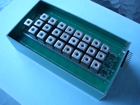
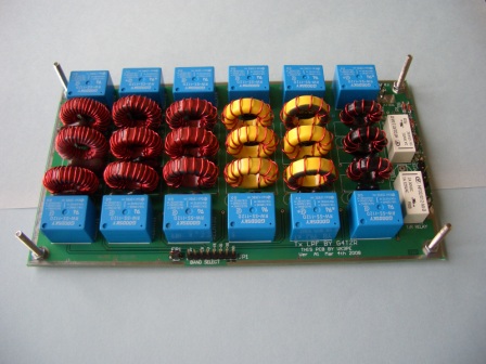
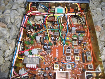
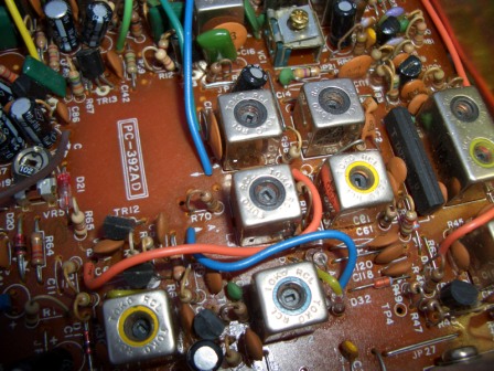
BPF
Holes for the Toko shield cans only need to be drilled out to 1.5mm or you can trim the Toko pin with a Dremel™ tool.
150W PA
A hole is missing to mount the BD135 (under T2).
LPF
The filter switching relays need to have a pin slightly bent, to insert them into the PCB.
"BPF" Panel contents and Links to build information:-
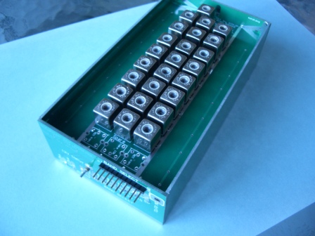
Band pass Filter updated 5th may '08
(5 PCB's) for STAR as original, but based on G6ALU SMD version, with added reed relay (on Rx input).
10th Aug, 2008: COIL WINDING using ex CB formers.
Glenn, please find attached my completed (well 99%) bandpass filter. All coils are ex CB coils.
With the exception of the 160M band coils all are 3 layer plastic former sections and the 160M is a 4 layer. All Capacitors are exactly as per schematic +/- error measurement.. As you can see nearly all coil trim positions are approx. identical in height, well 3 exceptions.
Just a quick note on each coil ferrite cup colour.
1. The blue appears to be a better mix for the lower freq. And the former has a 4 level former for greater turns, I guess a mix 57 or higher.
2. The orange is a better mix for general use 3 to 30 MHz this has a former with 3 layers, 1 to 30 MHz, a mix 43, I think. All coils same make-up
3. The light brown and red ferrite cups, have a slightly different mix, more suited to higher Freq, my guess 10-50MHz about the same mix but orange is also OK.
The biggest differentiation was the blue cups, to the rest. Also many coil cups had different colours, purple, yellow, green (white = no outer cup) mix between these did not vary much, but the internal connection, taps turns ratio and added C appeared to be the reason the colour code definition.
I will put the lot on a spreadsheet for distribution. Please do not hesitate to share this around.
Cheers all. Regards Gerald VK3FGJM
Pictures of Geralds CB type Coils in the BPF 809kb PDF
Picture of a CB with typical coil formers
Geralds Winding information soon
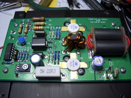
G6ALU's 150W Amplifier.
Steve, G6ALU has full information of his PA on his web site which should be used as the primary reference.
It may be accessed via the "Links" on the Yahoo STAR site.
A hole is missing to mount the BD135. Details in link below...............
150W PA, VK3PE build Updated on 10th Aug, 2008
G4TZR's Low Pass Filter. VK3PE build info.
Ray, G4TZR, has kindly allowed me to copy his LPF design which can cope with 140W plus.
Steve's (G6ALU) web page has details of the LPF which should be used as the primary reference. See "Links" on PICaSTAR Yahoo.
Bonus PICnMIX (VK3PE version).
Two PCB's, one is the 'front' panel pcb, the other is the Butler board.
The front panel board has had the BC327's corrected. Insert the parts as per the PCB overlay.
On this "B" version PCB, the overlay IS CORRECT. This is the prefered PnM board to use.
The 10R resistor feeding the 5volt 7805 regulator has been changed from surface mount to an axial resistor. (min 0.5W)
No link yet, until I get the documents ready (overlays etc) You can use the link to PnM on the Panel 1 page but be aware that the BC327's are now correct on this PCB !
Butler board is unchanged except that there is provision to also change the 10R feed into the 7805, with a leaded part (on bottom of PCB)
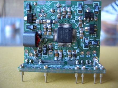
Bonus DDS board. VK3PE version, virtually identical to G3XJP's original version.
This board is the same as that supplied on panel #1. It is a bonus, to be used with the above PICnMIX PCB's.
The link here is to the original board.
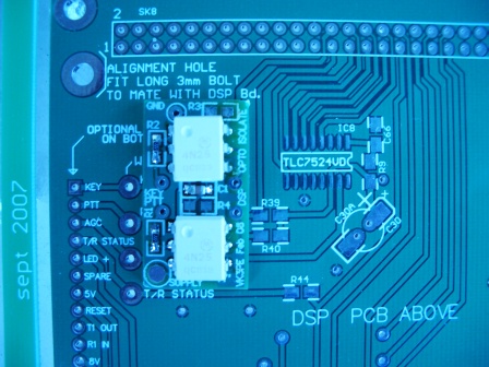
Bonus Opto Isolator PCB for PTT and KEY inputs to the DSP board. Reduces the risk of damage to the DSP chip.
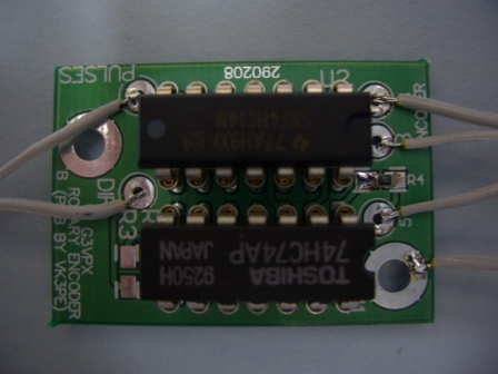
Bonus Opto Encoder interface for Avago™ or similar encoders.
(Use of other than the G3XJP encoder is not an "approved" mod for PICaSTAR, by the way.)
Bonus CODEC board with corrected footprints.
This new PCB is marked as version "B" and has the footprint for the CODEC and LM317 parts corrected.
This is the prefered PCB for CODEC.
Refer to the original documents for the CODEC until I can provide an updated overlay.
VK3PE
This page was created on 25th April, 2008
Last updated on September 1, 2020