CODEC Board, used in PICaSTAR
Last updated on November 8, 2008, Version "B" pcb added.
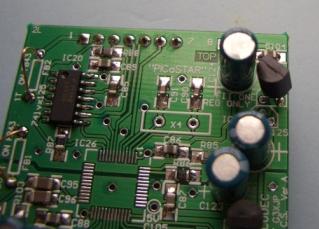
The 1st pictures are of the CODEC from Panel #1.
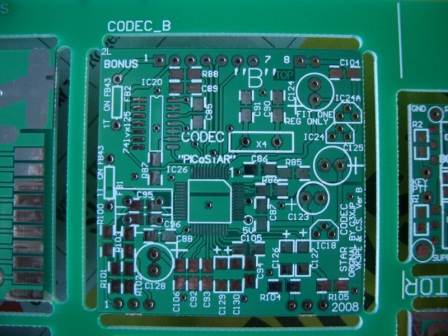
If you have Panel #2, use the "B" version Codec board from it, as the errors below have been corrected and the CODEC IC is easier to solder on.
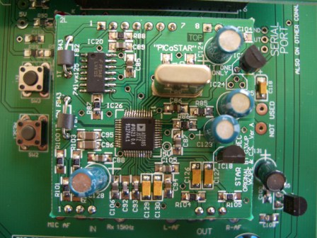
CODEC board shown part loaded, and almost ready for a power up test to confirm
the supply voltages are correct.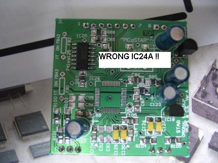
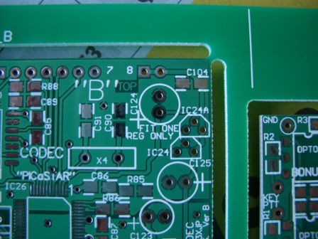
The alternate IC24 regulator (IC24A) has been fitted (but see below ) as the LM317L is easier to obtain than the LE33CZ part. Don't forget to fit the resistors on the other side of the board also if you use this option.
31-10-07 The footprint on the PCB is INCORRECT for an LM317 (alternate part to LE33CZ) {Version "B" is OK}
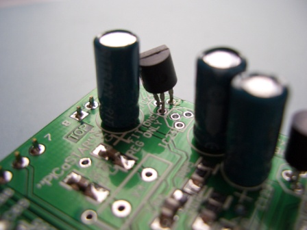
PLEASE NOTE: DO NOT insert the part as in the picture to the left !!! It is inserted INCORRECTLY.
See pictures (and overlay link) below for correct insertion. The part is inserted almost in reverse, with the centre lead going to the hole with the text "ONE" adjacent to it.
Wire links above will be replaced with ferrite beads.
When you fit the crystal, space it up slightly from the PCB or fit some insulation under it, to avoid a possible short to the adjacent capacitors.
The polarity of the 4 1uF capacitors is not marked on the PCB. The correct fitting is with the "bar" marking on the capacitors towards the top of the PCB. ie towards the marking "PICaSTAR". The "B" Version pcb has the polarity marked on it.
This type of capacitor is marked with a bar for the POSITIVE connection.
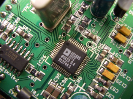
Fitting the CODEC chip:-
Use the thinnest solder you can find. I use 0.335mm solder which is the best I can find, but keep in mind that the pins on the CODEC are only 0.22mm wide and spaced at 0.5mm !
There is a slight runout of the pads when the CODEC is fitted on Panel #1 only. If you use the CODEC board from panel #1 then, align it on the PCB using the CENTRAL pins on each side first. Then tack one central pin, then tack the other side. Only then, after careful inspection, attempt to solder all of the pins. I use a very fine soldering iron tip of about 0.2mm but even then, it is easy to bridge adjacent pins. I used fine solder wick to remove the bridges. If you are unhappy with the pin alignment before soldering, you can nudge them slightly using a sharp dental tool or a needle (borrowed from your XYL's sewing box)
Use the CODEC PCB on Panel #2 (marked with a "B" as below) preferably, as it does not have the above errors.
If you are unsure or hesitant on soldering this chip, seek advice or assistance first.
 This is the
CODEC from panel #1
This is the
CODEC from panel #1
CODEC component overlay (panel #1 version only) pdf file 31-10-07
For the "B" version CODEC PCB on Panel #2, use the IC24a overlay on the PCB. It IS correct.
CODEC schematic pdf file 31-10-07
Updated on November 8, 2008
See also the DSP mother board section for a picture of the whole assembly.
Page by VK3PE