
|
Syntrx two way radio, Amateur conversions.Last modified December 29, 2022
These pages are now fairly old, so the info is presented as is by VK3PE (See QRZ.COM for email) Syntrx Service sheets (scans) for VHF and UHF maybe available on request. Both about 70Mb pdf files. ! Microphone only Schematic pdf file >>> Right Click to save NEW Dec 29th 2022 PL Board only Schematic pdf file. >>> Right Click to save NEW Dec 29th 2022
NEW a SYNTRX code plug (ROM) Windows Reader / Decoder program June 24th 2002 Try it and tell me if you like it. It will read any Syntrx *.prm style file. Use it to read and analyze these sample Syntrx files for 6 meters and UHF CB band.
UPDATED 6 meter band conversion added a) New Firmware (A brand new micro with new software programmed in)Updated 2022: NO LONGER AVAILABLE The Motorola series of Syntrx radios were made in Australia and sold on the local market from around 1985 to about 1995. The radio was very rugged, being built in a die cast chassis, and from all accounts, has proved to be very popular and reliable. They were available in the normal commercial VHF, UHF and 80MHz bands. The VHF version covers the Amateur 2mt band whilst the UHF version, in the ‘mid range’ and ‘low range’ versions, covers the 70cm band, without modification. I have developed all new software (programmed into a microcontroller chip) to allow the Motorola Syntrx radio or the Syntrx Plus version to be easily used on the Amateur bands, assuming the correct band radio is available. This new software does the calculations required for each channel and also contains frequency information for display, if needed, and repeater offset can be enabled on any valid repeater channel. A repeater “reverse” function is also a feature and scan facilities are provided. The standard Amateur CTCSS repeater access tone of 123Hz is generated and a time out timer is active on repeater channels. As an additional bonus, the new micro-controller also allows a Liquid Crystal Display (LCD) module to be simply connected to the radio, to provide a full frequency readout (e.g. “439.000” for the LCD, “9.000” for the LED) and also a mode display e.g. "439.375 Rx Smplx". This facility would also be useful, even if the controller microphone is available. Features of Amateur conversion to SyntrxNo programming software or cables required. Software in the new microcontroller is specifically for Amateur radio use. Receive coverage from 438.025 to 440.000 MHz (or 146.000 to 147.975Mhz if VHF radio, or 52.000 to 54Mhz if 6 meters) Selection by UP/DOWN switch on the microphone. Channel number indication on the microphone or actual frequency display if the optional LCD module is used. Transmit simplex as above or with -5mhz offset for repeater use. (only on assigned repeater channels) Automatic offset will be either +/- 600khz on 2 meters. The middle switch on the microphone selects simplex operation when centred and repeater offset when in the down position. Scan all channels from 438.025 to 440Mhz. (or VHF as above) The middle switch should be placed in the UP position to initiate scan. If the scan continually stops on a channel of no interest or is always busy, briefly press the UP switch when stopped on the nuisance channel, to delete the channel from the scan. Up to 10 channels may be removed in this fashion. To clear this “nuisance channel” list, briefly press the DOWN switch when scan stops on any channel.. Reverse operation. i.e. ability to listen on repeater input frequency. This mode is selected (on repeater channels only) by pressing and holding the microphone “S” button (or “call” button on some models). Not valid in scan mode. In simplex mode this switch may be pressed to open the squelch in order to hear a noisy signal below the squelch threshold. CTCSS tone of 123Hz is generated on repeater channels for tone access. Deviation level (nominal 500Hz) is controlled by R762 on the CTCSS board. LCD display module may be connected for display of frequency etc, with no additional circuitry required. Time out timer of 75 seconds on repeater channels only A version for 6 meters is under development with the same features as above.
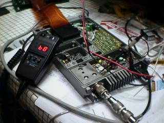
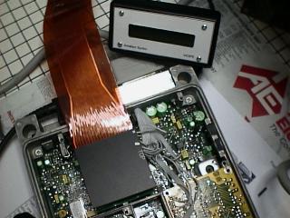
Software under development. An in-circuit emulator is just visible in the top left corner, connected to the Syntrx by a ribbon cable. This allows the software to be written and tried in the Syntrx without having to program a new microprocessor each time a change is made.
A similar view showing the external LCD module connected. The finished software is programmed into a microprocessor. In a non surface mount Syntrx radio, an adapter board must be also made, as below. For Syntrx plus (surface mount) just plug it in with a couple of minor mods.
The picture show the (blue color) proto board I used which has a grid of holes on a 0.1" pitch and a small pad of copper around each hole, on one side only. (Dick Smith Electronics have a similar proto PCB, designated H5615 at about $8) I used fine wire-wrap wire to make the connections, under the board. It's a little tricky, but possible with patience and a fine tip solder iron. I'm sorry, but at the moment, I have no PCB available for this.
b) Programming the standard Codeplug I'm sorry, but I have no Motorola software to program the standard codeplug fitted to the Syntrx. You will have to approach Motorola or their service agents to do this.
NEW March 28th 2000 Having said that, I hope to have the S19 files for ham bands available here soon. c) Using an EPROM in place of the codeplug. Using a 2716 EPROM in the Syntrx. Feb 26 '99 Of course, you can program the original devices used in the radio, for the Amateur band. (see note above) The devices however, are getting hard to obtain (see section h at end of page) but an alternative is to use a standard EPROM. For example, a 2716 EPROM can be used by making a small adapter board so that it can be plugged into the code plug socket in the Syntrx. A BC548 transistor and two resistors are also required. (This mod is not for surface mount component Syntrx "Plus" units. They have re-programmable devices.) Here is how I did it. Make an adapter board with an 18 pin DIP plug on the bottom and a 24 pin IC socket on the top. Make sure it will actually plug into the radio without fouling on anything. Connect the following pins together.
add this circuit to adapter board This is my version below, using a homemade PCB. (I don't have any more! ) In Australia, boards may
be still available from mtdods@alphalink.com.au Contact them
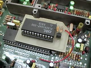
for details. ( Aug 2001) Note, in my case, I used a 2816 EEPROM in place of the 2716 device. These devices have no window and may be reprogrammed without having to erase them with a UV lamp. The red wire connects to a source of + 5V. This is a very early model Syntrx shown here, so DO NOT connect the wire as shown !
Here is a scan of the artwork. Be careful as the the scan
may have introduced some shorts between various pads. It's mainly shown
to give you an idea how I made a single sided PCB. Click to enlarge it. Artwork and schematic revised 11/11/99 All that remains is to program the 2716 using a suitable EPROM programmer with the data produced from a Motorola Syntrx programming program. d) Converting the Syntrx to 6 meters NEW page, Feb 2000 e) How to identify the UHF range you have NEW 16th Nov 2000 (thanks Kevin)
f) Changes required to convert Motorola SYNTRX Radio from UHF High band to UHF Low band. NEW 15th June 01
To adjust Rx. And Tx VCO's 1. Connect voltmeter to R230 (220K) near R127 IDC Trimpot. Transceiver should now operate and any adjustments to improve front end can be done. Regards, Mark (VK3ZR) g) How to identify what you have, from the micro part number NEW 8/12/2000
h) REMOVED NOV 2005 Unfortunately, some web surfers have expected more than they are willing to give themselves or are abusive when told there is no information available, so the link to a very helpful person and web site has been removed! Xxxx from company Xxxxxxxxx had gone to the trouble of having a PCB made for the Syntrx code plug (PROM) programmer. The original programmer was known as the ASC718 programmer and Xxxx has made a functional equivalent of this programmer using the ever popular PIC device. xxxx also has the original PROM's for the Syntrx, which suit the above programmer project. SORRY, BUT'S GONE! No guarantees are given or implied as to the suitability of this material for any purpose whatsoever.
Last updated on November 20, 2005 <>
|
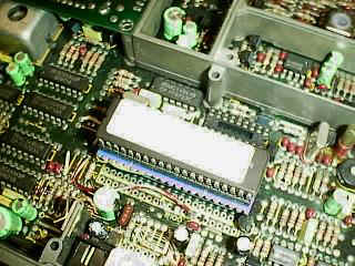 adapter board & micro fitted NOTE:- the PROM is removed from the
adjacent socket. It is NOT required now.
adapter board & micro fitted NOTE:- the PROM is removed from the
adjacent socket. It is NOT required now.  Note 2716-9 SHOULD BE DIP-9