LINKS:
Ian's (g3vpx) Trxavrb web pages
sample only !
Page created on 9th April, 2010.
Last updated on May 11, 2022 some build info added.
Background
These pages are general information
for the TFT pcb, for use with Trxavrb to control PIC-a-STAR. It is primarily
intended for members of the Yahoo® "Homebrew-radios" &
"Tfta_Central" groups.
The PCB is available through Gerard, VK3GRS see QRZ.com for email address.
You can also use TftA pcb for your own projects, see details below.
LINKS:
Ian's (g3vpx) Trxavrb web pages
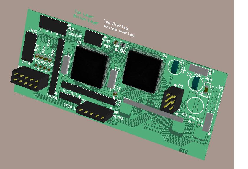
TftA PCB was developed by Chris S. specifically for using a TFT colour display (480x272pixels). Software is by Gerard, VK3CG or VK3GRS.
The PCB is available from Gerard. Contact him directly. Email is at www.qrz.com
Cost at time of writing, is a very reasonable AUS$5.00???? plus shipping (TBA)
TFT displays can most commonly be found in 4.3" (diagonal) and 5". The 4.3" for example, is commonly sold on eBay as a replacement screen for Sony PSP 1000. It has no touch screen. Typical cost is about US$20-25.
The 5" types are harder to find, but can be obtained in touchscreen or non-touchscreen versions. Picture below is without touchscreen (TS). A home made pcb carries switches to emulate TS.
2013: both 5" and 4.3" types with TS can now be found on ebay for around $20-30. Make sure you get a compatible type though ! Refer to the list on the Yahoo TFT_central group for details.
Display still has protective covering. Actual view is much better.
The interesting part of the TFT development is that it is not limited to use on Picastar.
If you have the inclination and some software skills, it can be used as a colour display for any project you wish.
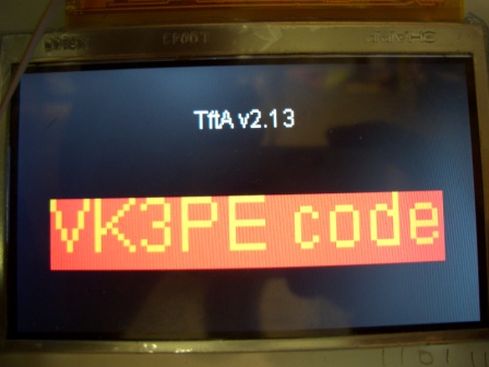
VK3PE has been playing with the display using a Motorola Micro (HC9S08QG8) to 'talk' to it, using assembler language. Examples are shown on this page.
The display uses I2C communications (2 wire serial) and the commands will be available shortly.
I changed to the QG8 from Freescale as it has an IIC port which simplifies things a bit. It might also be possible to use some of the Micro's that support programming in BASIC. eg PICAXE™
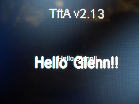 Playing with text sizes
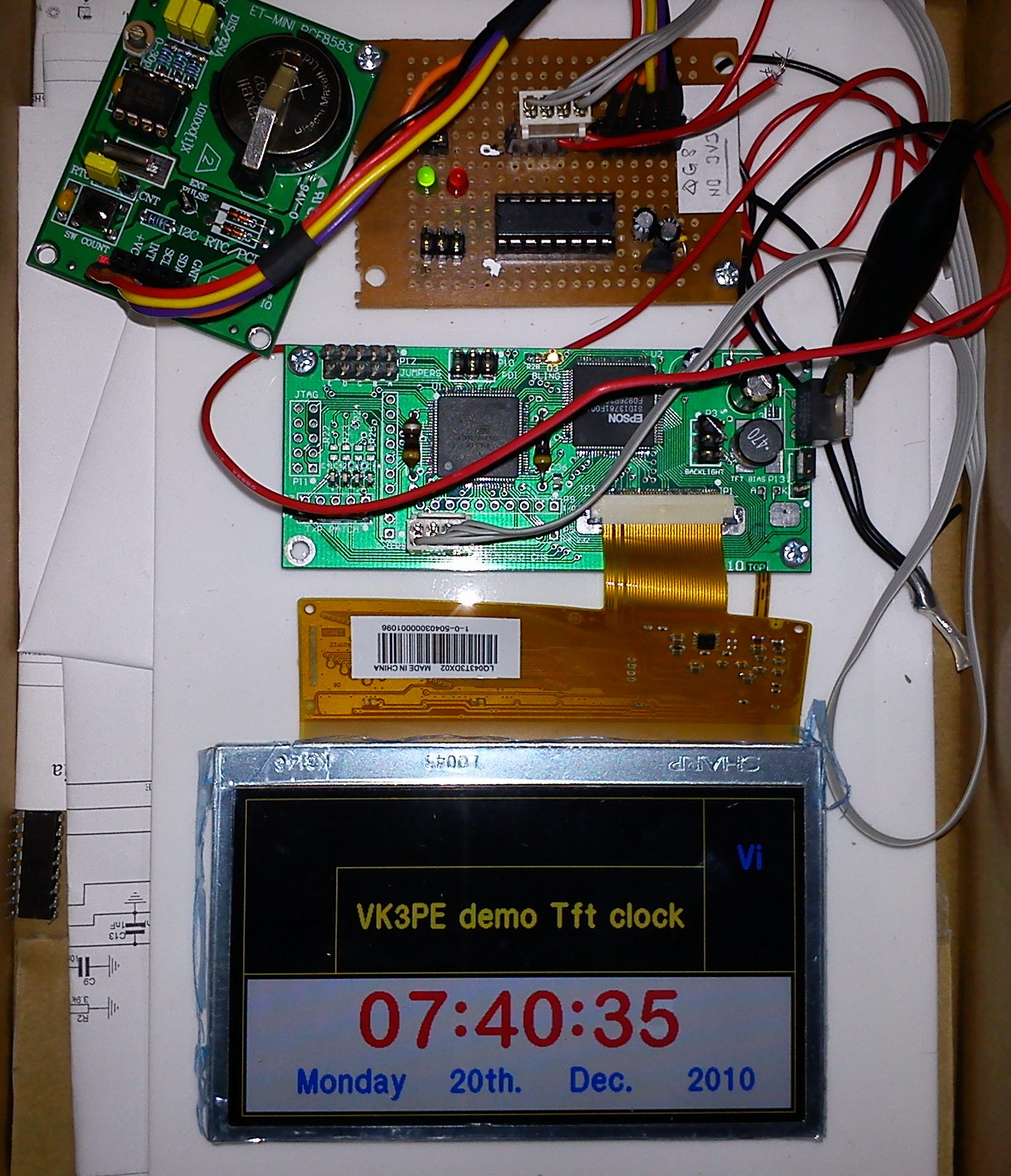
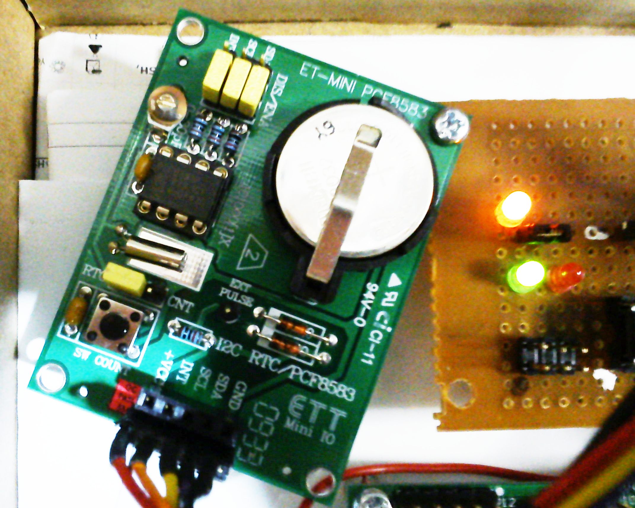
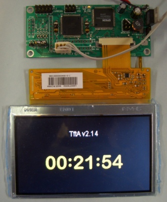
This is my setup, above. Top left is a little PCB with a real time clock (RTC) on it. To the right is the 9S08QG8 Micro built on proto perf board. Just the micro and a 78L05 voltage regulator. It has 8kb of flash memory, plenty for this project. In the middle is the TftA pcb and below is the 4.3" Tft display from a Sony PSP1000 handheld playstation.
As you can see, I have drawn a few lines, some text, and implemented a clock using the RTC pcb (from Futurlec). The Tft and the RTC are connected using the serial I2C lines. (ie data and clock) The RTC is read and the date and time etc are extracted from it in BCD format then re-formatted into text to display on the TFT in the bottom half. This is only the tip of the iceberg on what can be done. Just up to our imagination really, what can be displayed.
vk3pe
TftA Build information:-
Known problems
None
UPDATE 11th May 2022:
This is a very old project and unfortunately all of the build information was on a Yahoo Group which is defunct now.
I have tried to find as much information as I can and it's linked below.
(Some other info/links on this page may be obsolete. )
Bill of materials (BOM) Right click Mouse to download XLS file
Schematic Right click to download pdf file.
Software
Integration see below ZIP.
All info ZIP file. 5Mb file Right click to download.
Refer to Yahoo "TftA_Central"
group, files section.
VK3PE's "Manual" for TftA PCB v2.2
This "manual" is for the assembly and commissioning of the TftA PCB v2.2
Last update on June 3, 2010 At end of page, 5" display types clarified
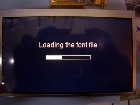
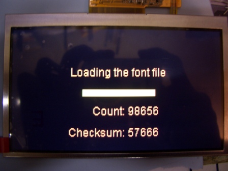
June 2, 2010 Added font load screen pictures
May 27, 2010 removed D2 in table at end. Overlay by value updated.
May 24th, added information on alternate programmer
May 15th, 2010: corrected fonts name and location
Please note, this is a draft procedure written by VK3PE. Some of the documents below are by VK3PE.
It is NOT the official build procedure, but was derived from two builds by VK3PE.
What you need for this project:-
1) A suitable TFT display of 480x272, either
4.3" or 5" (details in Appendix C)
2) TftA PCB v2.2 and all parts applicable to your build options. Refer
to BOM "BOM_Tft6b.xls " (New 11th May 2022) for details.
3) Integration drawing:- "? to be advised ?.pdf"
4) Connection details for common TFT displays Interconnect+ts.pdf
& Interconnect-ts.pdf See "Tftcompare.xls"
also.
5) Tft cable interconnect drawing "TFT_cable_200410.pdf"
6) Drawing for switches to replace TFT sofkeys. "Tft_M_BD__240210.pdf"
7) TftApcb v2.2 Schematic:- "Tft6bSchem.pdf" NEW May 11th 2022
8) TftApcb v2.2 overlay by component value:- "TFT
v2-_Overlay-values_270510.pdf" This drawing
shows all parts. NOTE, that according to
the build options, some may not be fitted (refer to BOM and Schematic.)
9) An existing (assembled and working) TrxAVRB
control board.
10) AVRISP2 programmer (Atmel or equiv.) see programming notes.
11) Software:
a) TrxAVRB software version 1.50 or later. Refer to G3VPX (Ian) web pages.
b) TftA V2.2 PCB software version TftA 2.xx
or later. (xx changes per updates)
c) Tft fonts file:- TftA.DF Refer to TftA_Central file area.
d) Hobcat by G3VPX, installed on your PC and a USB link to TrxAVRB
e) AVR Studio 4 software for PC http://www.atmel.com/dyn/Products/tools_card.asp?tool_id=2725
17th May, 2010: New drawings:- I have uploaded two new drawings to the Tft_Central group, files area (build info). These are for interconnecting Four Encoders and 2x6 keypads to the Tft PCB.
Documentation and TftA software for the build, is
located at "TftA_Central"
(Yahoo Group) You will need to join this group for access to files.
http://groups.yahoo.com/group/TftA_Central/
Documents in above list, in blue text, were produced by VK3PE.
Components: The official BOM listed above gives typical part numbers and reference to Farnell items as an aid in purchasing. For many parts, there are also other alternatives that will work.
General assembly information.
TftApcb can be built with several variations, to suit the type of TFT display and touchscreen or not. Also, Encoders 8 can be used instead of Trxavrb. Details are included in the BOM, schematic and this 'manual'.
It is suggested that low height parts are fitted first, including regulators, then power up and check voltages, before fitting the IC's. Do not fit any tall parts adjacent to the 2 large IC's initially either, like connectors or electrolytic, on the top of the PCB.
Since your TrxAVRB assembly included fitting devices with many fine pitched leads, it is assumed you will have little difficulty fitting the two devices on TftA PCB v2.2.
If you are using touchscreen, then an FSA2467 device will be fitted. Most will not be familiar with soldering this type of package. Gerard offers this advice for soldering the FSA2467 (only required for touch screen). As this is a package without “gull wing pins”, use plenty of flux and use the soldering iron to heat the pad until the solder reflows to the chip pins. Or use solder paste and heat appropriately. (with a heat gun perhaps)
NOTE:- Do NOT fit a link into the "K1" position adjacent to P6
If you are using a TFT display with touch screen, then resistors marked as "TBA" on the schematic will need to be calculated to ascertain the correct value to be used. Refer to Appendix "B" for details. Also, for touch screen, an additional Capacitor should be fitted in parallel with C37. It will need to be soldered over the top of C37. See BOM for value.
The value of R9 needs to be calculated for the display type being used. It depends upon the backlight current allowed for the display. Refer to the data sheet for the display used.
The Formula is R = 300 / BL current (mA)
For example, a Truly branded display is rated at 2x15mA max. So, R9 = 300/30 = 10R
For other types, check the data sheet. Typical values though will be given in Appendix C
Fitting of R14 and D2: See Appendix C also.
(And Tft_Central group)
The links shown above are for the VK3PE build only, which was for a "Truly " branded TFT display. You must only install the links required for the actual TFT display type you are using. Please refer to the "Integration drawing" for more details. Although this Truly display has touch screen capability, it has not been optioned onto the TftA PCB build shown here, so some parts on the left side (and on the bottom) have not been fitted. Refer to the BOM for details of touch screen parts fitting.
Fitting of "L1". There are two holes available for fitting L1 at the end adjacent to P9. If a touch screen TFT is NOT being used, then use the inner hole as per the picture above. Conversely, if touch screen IS being used, fit L1 into the outer hole. This is also shown on the schematic.
 I have used 'jumpers' from an old PC motherboard. Because it is very easy
to get the connections wrong if the jumpers are removed again, it is better
to use wire links. For some options, it is not possible to use the links
anyway as the connection is not the right spacing. The above picture may
NOT be applicable to YOUR build. Check the documents ! Please refer to
the Tft_Central files Interconnect+ts.pdf and
Interconnect-ts.pdf for information on PCB loading options for
the various types of TFT display that can be used.
I have used 'jumpers' from an old PC motherboard. Because it is very easy
to get the connections wrong if the jumpers are removed again, it is better
to use wire links. For some options, it is not possible to use the links
anyway as the connection is not the right spacing. The above picture may
NOT be applicable to YOUR build. Check the documents ! Please refer to
the Tft_Central files Interconnect+ts.pdf and
Interconnect-ts.pdf for information on PCB loading options for
the various types of TFT display that can be used.
Commissioning:
Power up the completed PCB initially from
a 12v supply connected to P4- pin 3, GND to pin 2. Do not use pin 1.
The backlighting might flash on briefly (white blank screen), this is
normal.
Programming the XMEGA128a1.
NOTE: a genuine (see below) Atmel AVRISP2 is required to program the device. It can also be used to program the Trxavrb. The AVRISP2 is available from:-
1) Farnell , part# 1135517
2) Mouser Part #: 556-ATAVRISP2
3) Digi-Key Part Number ATAVRISP2-ND
4) should also be available from Atmel distributors
There is now also a Clone AVRISP available for around US$30. This device
has been tested by Gerard and found to be OK, but requires a firmware
update to correct the programming for the Atmega128A1 device. This has
been communicated to the supplier and new purchases should have the new
firmware. If not, their web page gives information on the upgrade. If
you are interested, check this web page:
http://tom-itx.dyndns.org:81/~webpage/boards/USBTiny_Mkii/USBTiny_Mkii_index.php
Pre-programmed devices (Atxmega128A1) might
be available from the TFTa v2.2 group. Obviously, this will mean that
your TftA pcb will only have the software version current at that time.
Programming Method:
You will need to install Avr studio 4 on your PC. Having built the TrxAVRB
PCB, which also has an Atmel device, you may have this installed already.
If not, check Ian's (G3VPX) web pages for installing this.
http://www.homebrew-radios.net/trxavr_picastar/trxavr_downloads.htm
Do not follow Ian's instructions for programming though, as the Micro
used on TftA PCB is different. You cannot use the PONYPROG programming
pcb or software.
Depending on whether you use the source code
or the tftavr.HEX file, then you may need to compile the source code initially.
(Details for compiling are not included here) Programming however, follows
this routine, assuming the use of the HEX file:-
Plug the 6 way AVRISP2 cable into the programming port of the TftA PCB
v2.2 USB side to the PC of course. Make sure you have pin 1 correct. If
this is the first time that AVRISP2 has been used, you may need to follow
the maker's instructions to install it first.
The green LED on the USB side of the AVRISP should be ON. If not, then AVRISP2 is not installed correctly. If the TftA PCB is off, then a red LED will be lit on the 6 way cable side. Otherwise, it will be green. {It will change to red while programming though}
In Studio4, click
Menu | Tools | Program AVR | Auto connect (or click on the IC symbol
with "AVR" in the menu bars.)
The programmer appears:
Click on the Main tab and select the Micro: "Atxmega128A1"
Click on the Fuses tab and tick the JTAGEN and EESAVE boxes.
Click on the Program tab and tick the Erase device before programming
and Verify device boxes.
Click the button to select the Input HEX file, then locate the tftavr.HEX
file using the "……" box to the right side.
Then, click on the "Program" button.
At the bottom of the screen, you should see the progress of the programming.
Once programmed, remove the AVRISP2 connection and power cycle the TftA
PCB ie power off, then on.
You should now be greeted with a message on your TFT display near the top and centre of the screen "tftavr v 2.xx" (or later)
As this is the 1st time programmed, a further message to "power cycle" will be displayed. Turn power off then on. This time, only the version message should appear. If you don't see this, check the "bling" LED on the top of the PCB: (See Appendix A for meanings of the LED flashing) If the LED is NOT flashing, you may have a problem with soldering a pin or similar on one of the IC's.
If all is OK so far, you can now connect the TftA PCB to TrxAVRB board. An I2C cable is required for this. Full details of the cable assembly are in drawing:- Tft_cable_200410.pdf (by VK3PE) Shown below is the cable, but please construct it per the drawing!
TftA PCB "J6" TrxAVRB "Jx1"
SDA 1 -------------------- 4
5v 2 -------------------- 1 no connection (link "K1" on TftA
PCB is NOT fitted)
GND 3 -------------------- 2
SCL 4 -------------------- 3
TrxAVRB needs to be set up to communicate
with the TftA PCB using the I2C cable, in the hardware set-up area of
Hobcat. (ie you need a USB connection from TrxAVRB to the PC and Hobcat
running)
Ian's web pages have information on setting up the TrxavrB hardware configuration.
http://www.homebrew-radios.net/trxavr_picastar/TP_setup_4_USB_data.htm
The assumption is that you already have another type of display fitted and will be changing over to the TftA PCB v2.2 ie, you are basically familiar with using Hobcat and Trxavr.
The top of Ian's page is applicable here. It is reproduced here for reference. For "EA320" substitute "TftA PCB V2.2" {non-applicable sections have been removed}
TrxAVR_Picastar setup instructions
- Configuring via USB
Hardware setup
Click Menu | Setup | Hardware config The hardware configuration window
appears.
It is shown below configured for EA320 graphics + touch panel + 25 key
pad.
You heed to configure it for your hardware by selecting from the drop
down lists.
Please do not select eDIPTFT43-ATP TFT or TftA PCB v2.2 colour (I2C bus)
with touch screen unless you have such a panel connected. ( This will
result if software delays associated with TrxAVR awaiting response from
an absent display panel. DSP load with take over a minute and the various
USB communications will be very unreliable. Fortunately, Hardware Settings
still works ok .. so you can change the display setting !!!)
SCREEN SHOT TO COME
Now, on power cycle, your TftA PCB v2.2 should briefly flash up "tft v2.xx" (or later) then a nice full screen of colour should appear ! You may notice that some text appears to be the wrong size. Eg the A and B VFO frequencies will be quite small.
Using Hobcat again, the fonts need to be
uploaded to TftA PCB v2.2. This only needs to be done once. This is
detailed on Ian's pages also at
http://www.homebrew-radios.net/trxavr_picastar/TFT-colour.htm
Right at the end of the page, the font's (.DF file) are selected and sent
to TftA PCB v2.2. While this is happening, a bar graph of the download
progress will appear on the TFT screen.
Power cycle your TrxAVRB/TftApcb again and the screen should now have the fonts correctly sized.
You can set up the back lighting maximum brightness and dimmed levels to suit your own preferences. Again, refer to Ian's pages for details:
Many parameters can be changed and the colour
screen brings a new dimension to using PICaSTAR.
See these pages http://www.homebrew-radios.net/trxavr_picastar/software_specification.htm
TOUCH SCREEN
The information above assumes a non-touch screen type of TFT has been
used. For touch screen, some resistor values on the TftA PCB v2.2 will
need to be calculated and fitted. Also, a calibration procedure has to
be carried out. See Appendix B for details.
ENCODERS 8
TftA PCB v2.2 also has provision for fitting up to eight encoders. This
facility is also provided on TrxAVRB and if you are already using them,
then no need to change. Encoders used are usually about 16 position and
often available on eBay (eg from "Sureelectronics") in lots
of 10. (One will be used for the "Menu" encoder on TrxAVRB).
To use up to eight additional encoders on TftA PCB v2.2, connect them
to the PCB as detailed in the Integration drawing (drawing name is at
start of this document) They may be assigned to the task required, using
the procedure here:
http://www.homebrew-radios.net/trxavr_picastar/Colour_TFT_images_screenshots.htm
Fitting TFT to your STAR project.
TFT displays are usually specified for 6 o'clock viewing. This is because most displays of this type were originally intended for hand held devices that are held in such a way in normal use that viewing is from the bottom or 6 o'clock position.
TftA PCB v2.2 has provision to 'invert' the display but the software has been written to give the best viewing angle, with the TFT flex cable at the top. See the integration drawing. Briefly, a link can be fitted on P12 at the "A" position to invert the text and graphics written to the display. The magic of software. Try it out. You must power down, then fit (or remove) the link first.
This determines how your display and TftA PCB v2.2 is physically fitted to your project so take it into account before making a new panel for fitting the TFT.
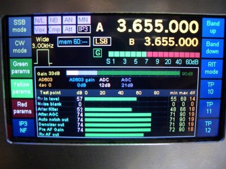
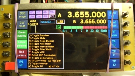
If your new TFT display does not have touch screen capability, then the soft keys (TP1-TP12, see picture below) visible on the display down each side, will require separate switches on the front panel, to emulate the softkey function. Paul, M1PVC and Glenn, VK3PE, for example, made a simple PCB to hold 12 switches, 6 down each side. Tactile switches and small knobs were fitted. The extra keys need to be called up in Hobcat as "6x6" matrix. Details of the connections are in the drawing listed at the start of this document..
M1PVC:- http://www.carnut.info/singleboard/Ver_B/BUILDERS/M1PVC/Paul_M1PVC.htm#paul
VK3PE:- http://www.carnut.info/singleboard/Ver_B/BUILDERS/vk3pe/vk3pe.htm
In the Hobcat hardware set-up, the "6x6" keypad matrix is used. The switches have to be allocated the functions of the appropriate softkey using the Menu encoder. Eg, in the picture below, the softkey "TP1" is first given a function like NF/IP3, then the switch is allocated the keypad matrix (ie X, Y value) mapping. The mapping letter ("o" to "z") into the X,Y keypad is shown in the drawing. More details to follow.
NEW ! It is also possible now, to fit the 2x6 keys directly to the TftA PCB instead of Trxavrb. This will be simpler in most cases.. Refer to my drawing in the TftA files area for build info:- "TftA-pcb_with_2x6_keypad.pdf"
There is also a drawing for the connection of the Encoders. Note you can also fit up to 4 encoders if you have fitted the 2x6 keypad as advised in the drawing.
The TFT was stuck to the PCB with double sided tape. TftA PCB v2.2 was
fitted on the rear using countersunk screws but tape could also be used.
< that's me with the camera ! >
Enjoy !
Diagnostics using "bling" LED: < Refer also to the official Doc "TftA_Bling_LED_Codes.DOC" on TftA_Central >
1) Normal - on (0.5S) off (0.5S)
2) Power cycle required - on (0.5S) off (1.5S)
3) Serial eeprom error - on (0.5S) off (0.5S) on (0.5S) off (1.5S)
4) Font load in progress - on (0.5S) off (0.5S) on (0.5S) off (0.5S) on
(0.5S) off (1.5S)
5) No I2C activity for last 60 seconds - on (0.5S) off (0.5S) on (0.5S)
off (0.5S) on (0.5S) off (0.5S) on (0.5S) off (1.5S)
The meaning of the (1) code - normal - is that I have passed initialization
and none of the following codes has/is occurring.
The (2) code - power cycle required - occurs when first powering up the
unit. The eeprom has to be programmed into 512 byte mode and this requires
a power cycle to take affect once the command has been sent to the eeprom.
This only occurs the first time the unit is powered up as the values are
retained permanently. If this occurred multiple times it would indicate
an eeprom problem.
The (3) code - eeprom error - is displayed if, when I do a read of the
device ID bits, I do not get the correct values returned. I read both
the status and manufacturer ID bits (which are 2 separate read commands)
so it is a good test. If you do not get this error code then the eeprom
is most likely working correctly.
The (4) code - font load - should occur during the font load operation.
If it does not occur then the font load process is not occurring - this
would indicate that the font load command has not been received.
The (5) code - no I2C activity for 60 seconds - indicates no valid I2C
activity. When connected to TrxAVRB, TrxAVRB continually sends I2C messages
to the display (ie TftA) to update the S meter display. If the (5) code
occurs it indicates that in the last 60 seconds the TftA has not received
any valid commands. By this I mean that it has not received valid macro
commands. This would indicate an issue with the I2C path.
Touch screen resistors
These resistors need to be calculated for the display you are using.
Refer to the information in the Files\Build
area of the "Tfta_Central" group for details.
Touch screen calibration
Details to follow in next revision.
Display types.
The TftA PCB V2.2 can be used with 4.3"
or 5" types that are 480x272 RGB.
For example:
1) Truly (4.3") TFT1N4633-E(4.3)V0.1.pdf
(has touchscreen)
2) Sony PSP1000 replacements (4.3") Sharp LQ043T3DX02_SP_122805.pdf
(no Touchscreen) Often found on eBay from US$25 but quality variable.
3) Chinese group buy by VK7MX, 5" with or without touchscreen: Buy
is now closed but also on eBay around $28
AT050TN33 v1.pdf 5" has no touchscreen
AT050TN33.pdf 5" with touchscreen
4) Other TFt's may be suitable, refer to "TftA_Central" Yahoo
group
Note supplied by VK7MX, 3rd June, 2010:-
AT050TN33 comes in two versions. AT050TN33 has an integral touchscreen,
AT050TN33 v.1 does not. This difference became apparent only after
protracted email correspondence with the supplier but you may rely on
it.
The AT050TN34 has an integrated touchscreen but we are not supplying that particular TFT. We were originally trying to obtain it but it proved too elusive. That is why no data sheet can be found for it on the group pages.
Best to confirm your TFT
type with others on the TFT_Central yahoo group. Many types look familiar,
and even the model numbers may be similar but one type OK to use, another
not.
Cheers
VK3PE
Data sheets for these displays will be available at TftA_Central (Yahoo
Group)
Backlight typical values for the displays above only.
| Display type | R9 | R14 | D2 | |
| 1) Truly | 10R | 0R | not fitted | |
| 2) Sony PSP 1000 | 12R | 0R | not fitted | |
| 3) Chinese 5" | 8R2 ? | 0R | not fitted |
LINKS:
NEW Homebrew group covers Picastar/TFT display etc.
http://groups.yahoo.com/group/TftA_Central/
Ian's (g3vpx) Trxavrb web pages