Paul, M1PVC has built three PICaSTAR's incl. Combo PCB versions.
17th October 2010 Paul's Combo made 1st QSO's !!
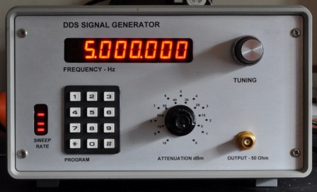
Last updated on February 22, 2011 Picture below of Paul's Sig Gen, made from Pic-n-Mix controller.
See below for Lodestone™ information
and Paul's Combo build with TFT display. Now on-air !
 Pauls Combo Star with TFT, 28-08-10 More Pics. below.
See also Pauls previous PICaSTAR build. and www.qrz.com
LODESTONE™ & Toko (Coil) WINDING
Update: 20th Feb, 2011. Paul now has a Tracking generator and has been optimising his Lodestone filters:-
60m is peaking too low so I must look into this (don't
use the band though)
30m is well down....suspect Lodestone windings are wrong
12/10m is peaking too high (31MHz centre) about 3dBm down but again Lodestone needs tweaking (but can get TOKO coils at £0.75 each). Would like to improve 40m but it's proving problematic even with the collect TOKO inductors......most strange. The Lodestone inductors for 160m seem to be inferior to the TOKO ones........perhaps these do need to be wound with Litz wire.
What I can say is that SA with TG works magnificently....and is extremely accurate. It's just a pity that I have to keep removing and refitting the Combo board so often whilst making these adjustments but I'll get there in the end
Might be an idea to either give a health warning or remove altogether the Lodestone winding details of mine that you have published on your site as I suspect that the details for 60, 40, 30, 17/15 and 12/10m are all in need of tweaking if the design caps are to be used.
See notes immediately below also for an update: <vk3pe>
Hi Glenn
UPDATED 25th Jan 2011
I have now received the TOKO coils and finished my testing and setting up of the BPF using a spectrum analyser with a tracking generator. I have found the following -
The Lodestone formers work well where the winding is in one layer i.e 20m and above. Below this, unless the former can be fitted with winding separators as with the TOKO formers, the multilayer winding due to self-capacitance results in the Q of the inductor being low.
The TOKO inductors as specified by Peter (XJP) give much better results on the lower bands but I have found that the T1014Z coils specified for the 30m band have too much inductance and insufficient tuning range........I have used TOKO 10.7MHz IF transformers stripped and wound with 33 turns for this band.....even so the insertion loss is 10dBm due to the fitted 10.7MHz IF trap.
Insertion losses now are as follows -
160m.......XJP specified inductors.......4 dB
80m ......Lodestone formers................4 dB
60m.........XJP specified inductors.......4 dB
40m.........XJP specified inductors.......6 dB
30m........Rewound TOKO IFT's..........10 dB
20m........XJP specified inductors........3 dB (Lodestone formers 4-5 dBm)
17/15.....XJP specified inductors....... 4 dB (Lodestone formers similar)
12/10m...Lodestone formers.............2dB
I attach the revised Lodestone winding schedule to replace the current one on your web pages however I am not generally impressed with them as in most cases the TOKO coils have proved superior.
Here are the new Lodestone winding details
Those are the results though the whole of the BPF.....actually the FST3126's seem the work exceedingly well to my surprise as I thought these where causing losses but they do not. yes 30m could be improved perhaps with a better IF notch (or different IF)....I will just accept it as I do not use CW so 30m loss is no problem to me. In the test jig without the trap the results were about 6-8dBm down........this is presumably why some have opted for toroids in this position...
Kind regards
Paul M1PVC
4th Feb, 2010: Paul has wound his Lodestone formers. The information was derived by Paul as below.
Hi Glenn
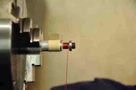
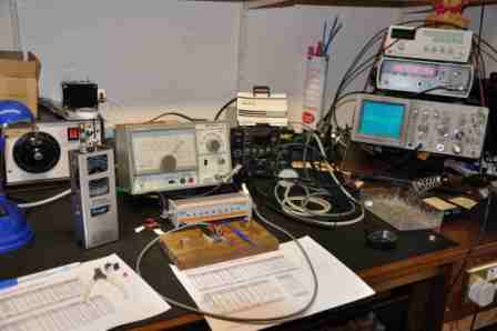
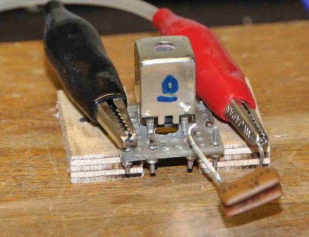
Think I've cracked it as shown in attached photographs. I turned up a mandrel in the lathe to hold the Lodestone bobbins safe and securely, put my hand crank on the lathe headstock and used the lathe as a coil winder. A little bit of stick on the windings to hold them in place allows the formers to be assembled with ease without those pins getting in the way. I do not have an accurate inductance meter for the low levels of inductance required so I made up a jig to connect up the assembled coil (using pins from a turned pin ic socket), produced a self calculating Excel speadsheet to find correct tuning caps, sorted out suitable test caps accurately measured on my Marconi bridge and checked to resonant frequency of each inductor. Started using my dip meter but it was easier to use a sig gen, frequency counter and 'scope all as shown (this particular sig gen is a bit of a joke but used with an RF attenuator it does the job and it's small).
I've wound the inductors for 160, 15/17 and 12/10
so far but I have ordered some 0.2mm wire for the rest - hopefully this will
come
tomorrow. Seems that my previous calcs are in the right ball-park but need a
few tweaks. When I've done the whole batch I'll revise this and send you a copy.
Cheers, Paul
15th March, 2010
Hi Glenn
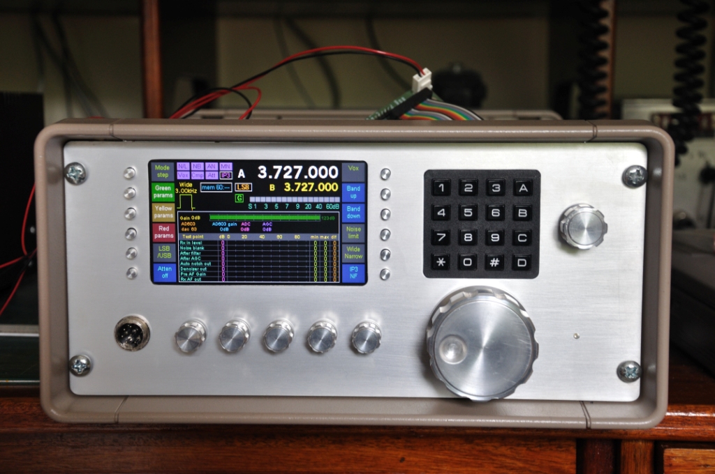
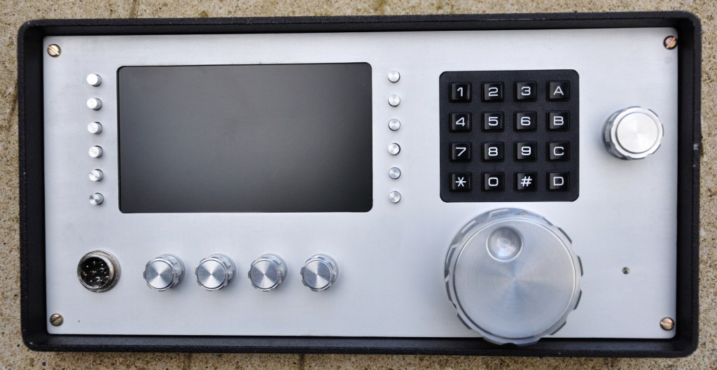
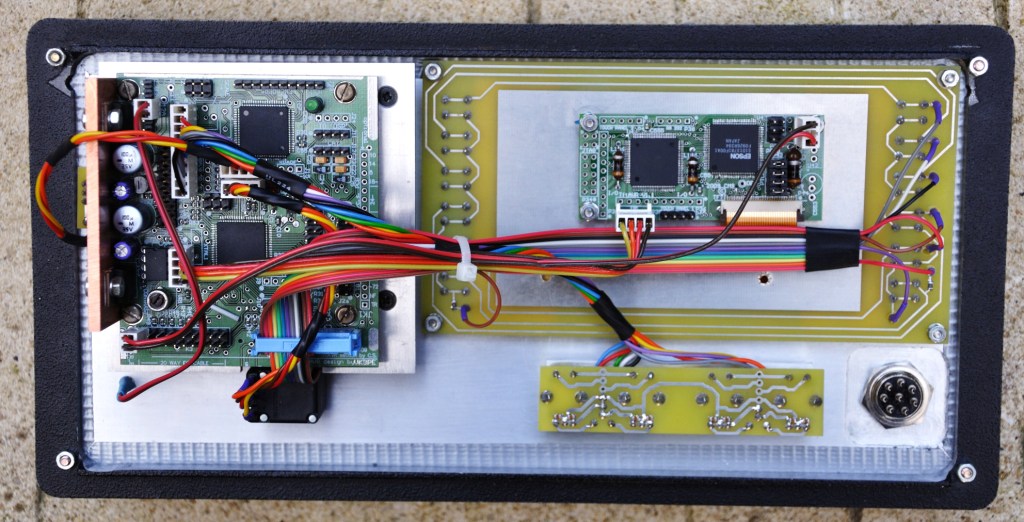
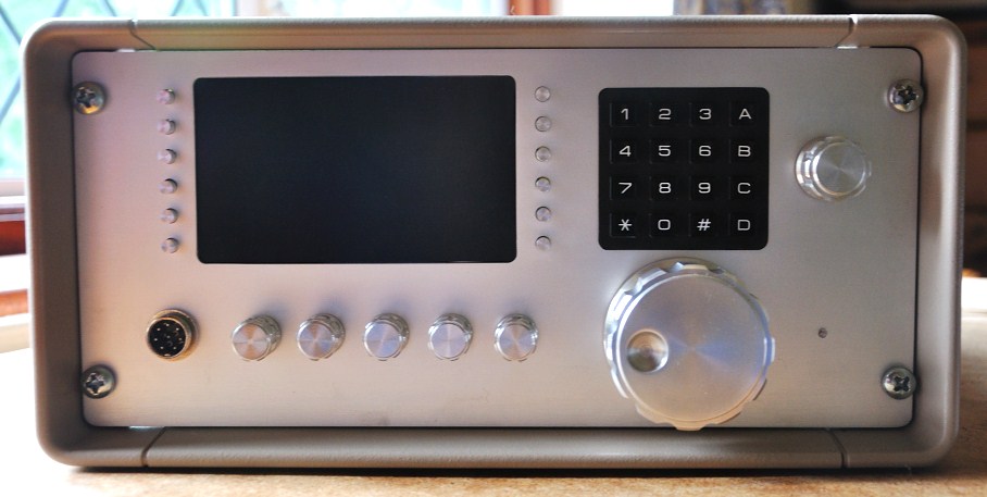
"Two pictures of construction so far on front panel...this has really taken some time. Designed to be a complete TrxAVR controller assembly with rest of ComboStar mounted behind and separated by a full height full width screening plate....I have 50 mm spare room in case depth to allow this installation....just enough! Assembly uses "cut down" version of TrxAVRB board including encoders8, Mk1 TFT driver board, 5" TFT display (without touch pad), 8 "label" buttons, menu encoder, tuning encoder, 4 parameter encoders, mic/headphone socket, and dsp led (to right of tuning knob). Front panel dimensions are 275mm x 135mm high excluding bezel. As before all knobs and button caps have been turned up from aluminium stock. Tuning knob is 55mm diameter.....the largest size that wound fit the situation....the weight of this gives the Bourns 128cpr encoder a superb feel. Both front panel and sub-front panel have been anodized with panel markings still to do"
Very pleased with the way that the display has mounted now with the connector "ribbon" behind the pcb and though a slot (hidden by the rest of the wiring) straight into the driver board socket. Button caps were a pig with each one having to be finally hand reamed out to fit the individual switches with all proved to be very slightly different in diameter. However I did manage to make all of the other knobs in one day...getting quicker!!
Paul
In case you missed the details above, Paul has made all of the knobs himself, including the tiny 12 that run down the sides of the 5" colour TFT display. (vk3pe)
< Click for larger pictures >
26th August, 2010:
Hi Glenn
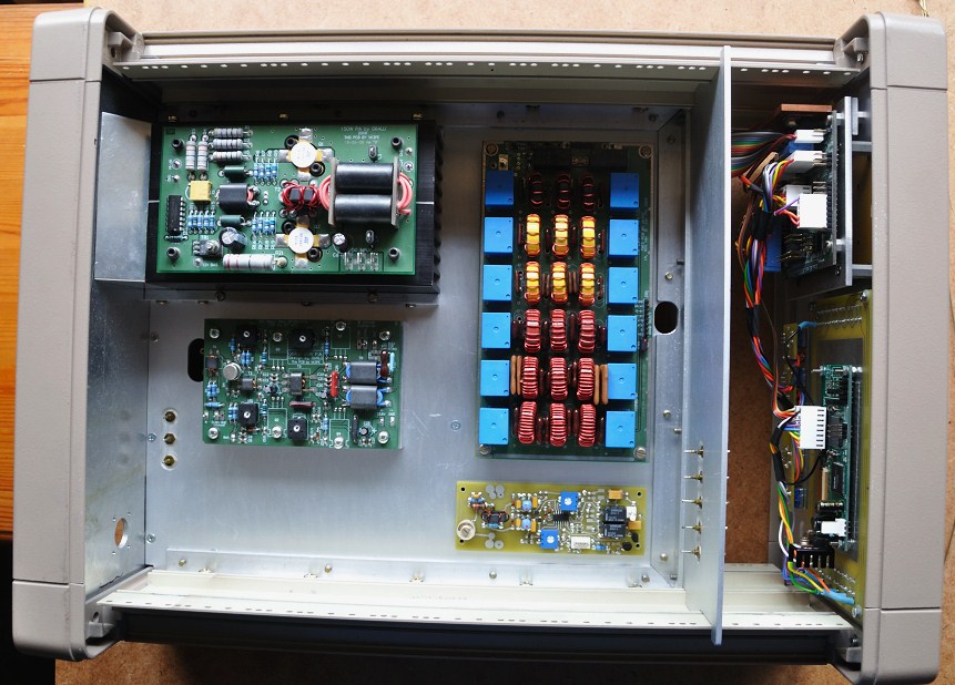
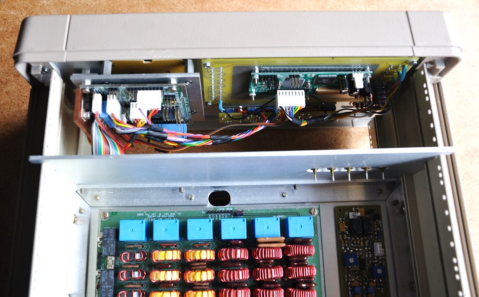
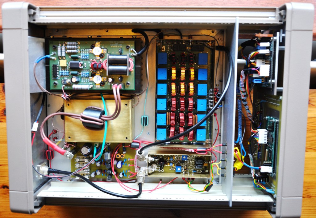
Well I'm at last moving forward again so I've attached
some pictures of my progress so far using the newly acquired
instrument case. I now have to finish off and anodize the rear panel which needs
further connectors added for USB, RS232 CAT and maybe switching and band information
for external PA and also DC power input provision. Screened enclosures to RF
deck boards to make and fit. All integration wiring to combo panel and RF deck
and power distribution board/fan controller and wiring. Then a lot of testing
and commissioning required and combo board screens....and front/rear panel graphics......should
keep me busy for some time at my present rate of construction but all good fun...
Cheers
Paul M1PVC
Fantastic work by Paul, Click image for larger pictures:

17th Octber,2010
Paul's Combo is his 3rd Star and made first QSO's. Very nice build, Paul. <vk3pe>
Nov 2010:
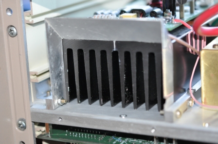
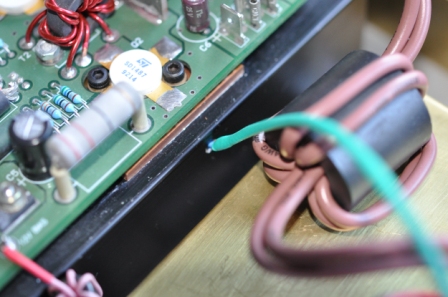
Hi Glenn As I have the rear panel removed I took the two attached pics to show you details of the "shroud" and the hole that i drilled for the thermistor carefully located to come as near to the devices as possible but also to miss their fixing screws. As they say a picture is worth 1000 words.
Paul
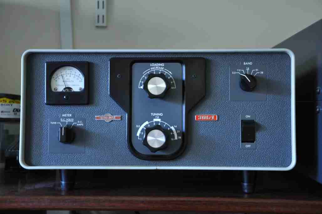
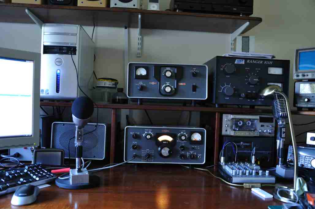
Paul has restored some Collin's™ gear to as new condition in his spare time and worthy of some pictures here. Very nice. What you can't see is the amount of work Paul put into the restoration, apart from the end result of course.
Hi Glenn
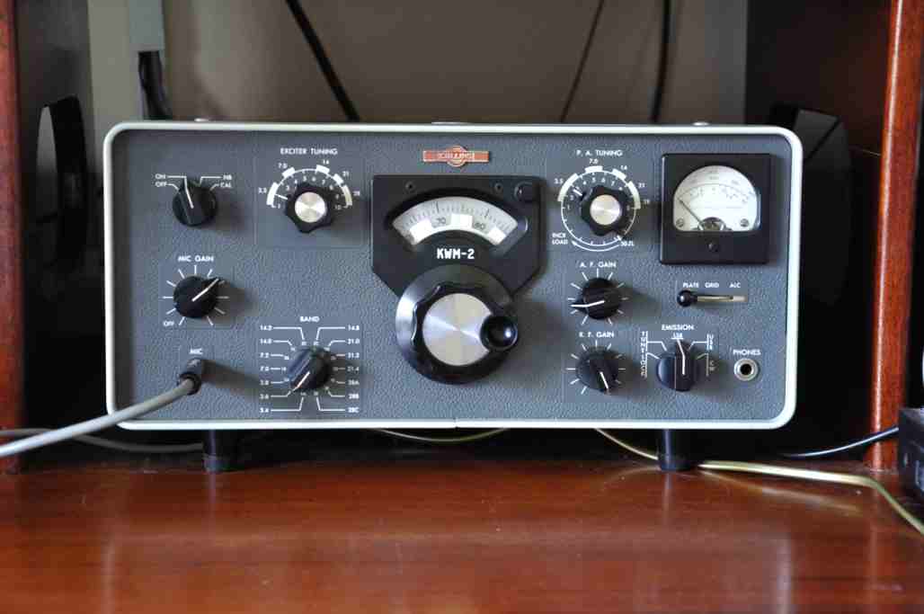
Herewith part of my boat anchor collection.....the
KWM2™ with the matching 30L1™ Linear Amplifier. Bought both a few
year ago - Linear first them KWM2 and refurbished them. They now perform very
well.
Paul
M1PVC { 24th Jan 2010}
Click for larger pictures.
Back to:
Combo AA (proto "Combo")
Page created on 24th Jan 2010