PICASTAR PCB, Combo Vers "CC & C2a" by VK3PE
These versions are very similar, mainly minor updates.
IMPORTANT:- You MUST be a member of the Yahoo™ 'picaproject' Group for access to the latest files and software and to purchase these PCB's in the group buys. You need to join this group and digest all the information contained there on the project and especially the set-up information. Picastar was designed by Peter, G3XJP, who wrote a series of articles which appeared in RADCOM magazine.
You need, at the very least, to have read through these articles, for the backgound information, setup procedures and design details. In addition, information on coil and transformer winding is contained in those articles, that are now duplicated on the PICAPROJECT Yahoo Group pages. This group is not active as a reflector, it only contains files.
Last updated on:- November 4, 2015 removed no longer relevant text etc.
The 'a' suffux means that the PCB has provision for a RTC battery charger. All else is the same as the C2 version on this page.
THIS IS NOT A KIT. JUST THE PCB's. THE BUILDER NEEDS TO BUY ALL OF THE COMPONENTS HIMSELF.
vk3pe AT bigpond.com
What is this "Combo" project page about ?
Feb 6th 2012:-a bug on C2 boards in Timer area.
Jan 17th, 2012 Updated, Please see BOM, Schematic and Overlay sections.
Dec 19th, 2011:- added info on fitting MMIC instead of 2N3866......
*** Dec 15th, 2011:- sorry to say this, a 'Bug' on C2 PCB.
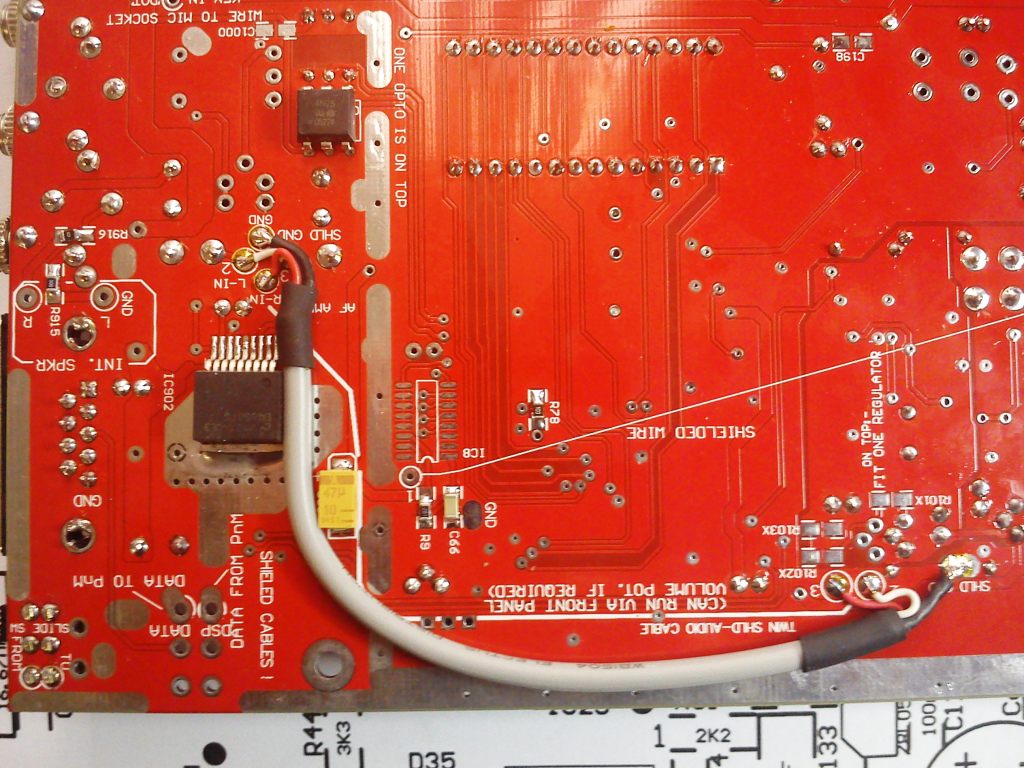
Dec 12th 2011:- I don't intend to build another Picastar, but I couldn't help assembling the AF amp and DSP area on the new RED "C2" boards! It took about 2-3 hours and the LED flashes ! The DSP code loads also. I then made the shielded cable to connect DSP to the Audio amp stage, pictured, and was greeted with the Morse "Hi" (it works) The speakers plug into the top stereo jack.
. < Click pictures for larger size. > sharp eyes will see that a resistor in the AF amp is missing in this picture. You might notice when you receive your boards that the overlay may be displaced to one side a little. It seems to vary from board to board on this batch only. Out of my control but the vendor has been notified and apologised. It won't affect construction though.
Since then, I added all of the other parts that I had in 'stock' apart from borrowing a filter from another star, to complete the PCB and it is now receiving signals !

In the picture above, the monitor switch uses a slide switch instead of a toggle type. There is provision on the PCB for this switch although it may be hard to find exact type available in VK. The serial data cable to the Travrb must be terminated on the switch, depending on which one you fit. It is marked underneath..
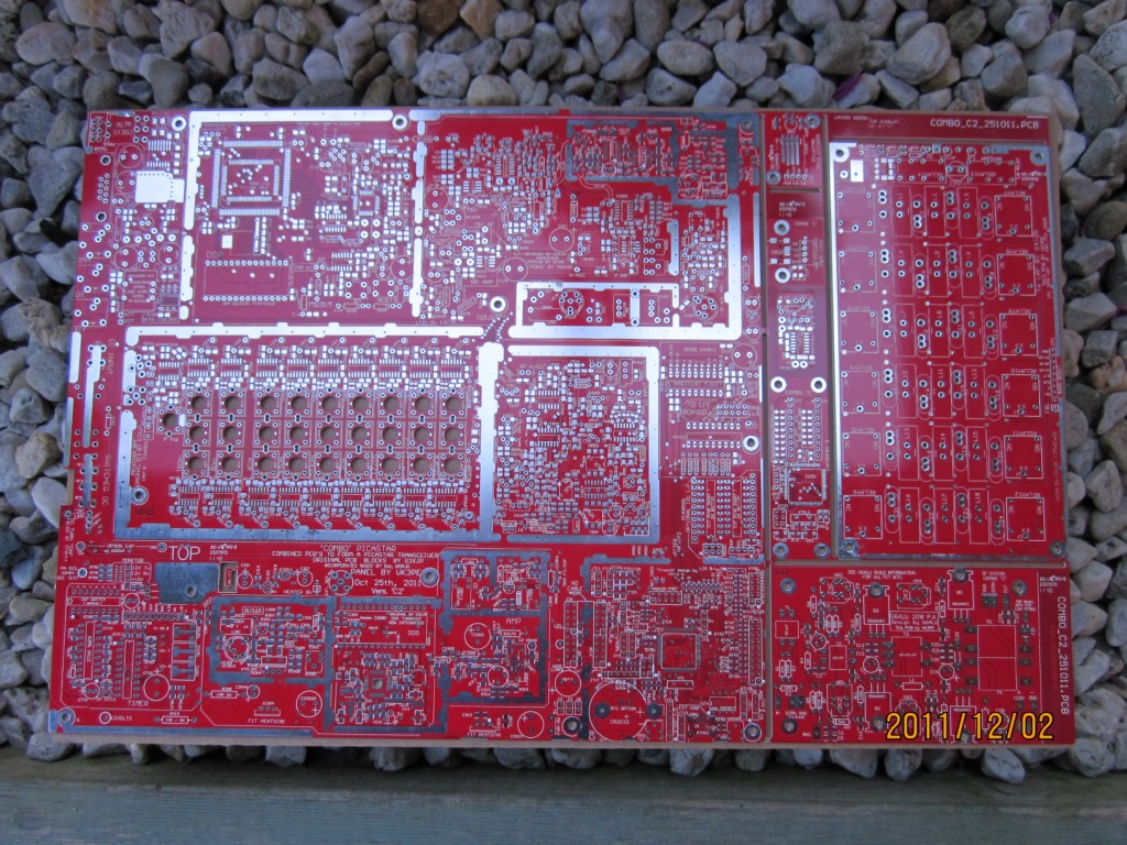
The panel of PCB's is 410 x 260mm. Another PCB for the 140W PA is not shown. < click for larger size pictures. >
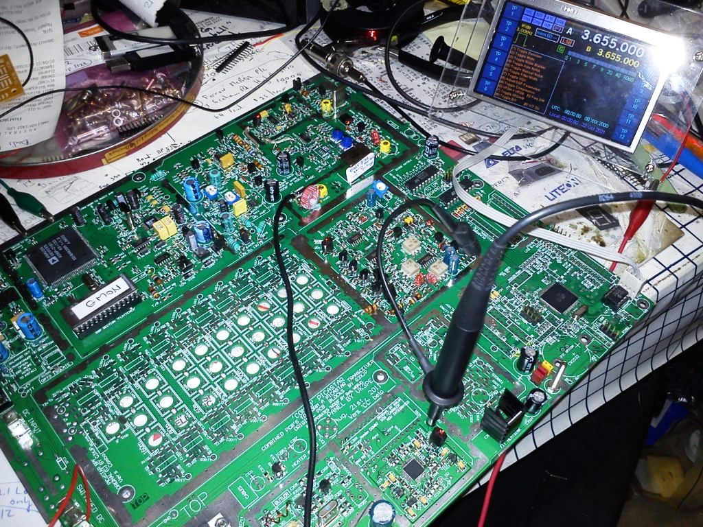
10th Oct. 2011 VK3PE's Vers "CC" build (the green board) is now ON the Air !!
Oct 10th, Real Time Clock fitted
26th Sept, BOM updated.
Previous updates:- error page updated, some PCB's available, building progress, pcb's arrived
PICaSTAR is a full Multi band HF transceiver designed by Peter, G3XJP, for home construction. It is NOT a kit !
Peter's original design is based on a number of separate functional PCB modules, wired together. This "Combo" version combines those modules into a single PCB. (Less PA's and LPF but these boards are supplied also)
The Combo Version "BB" has been built by a number of people in order to build a PICASTAR transceiver a little more easily, as most of the circuitry is Combined into one large PCB panel. Although this may restrict the experimenter from using different circuit blocks, most people tend to build STAR to the original design by G3XJP which is substantially replicated by the Combo version.. The "Combo" version simply integrated all the circuit blocks into one PCB, mainly to reduce interwiring chores.
Over a period of time, vk3pe has been updating the Combo BB version into a new "C" version.
This is to make some areas a little easier to assemble, but mainly to provide for Bob, M0RJD's improvements (optional fitment) and to integrate the TrxAVRB PCB into the Combo panel as most builders use this controller designed by G3VPX. The PCB layout in this area is based on work by Chris Stake. Primarily, this version "C" is aimed at builders who use the Tft_A display (also designed by Chris), although other LCD displays can still be used.
On-going work on the project is now completed after a number of months work and a small 'proto' run of PCB panels was ordered to assemble and check the PCB. This was Version "CC". Dec 2011:- The current version is now "C2"
Shielding of the various PCB sections is also required (as was the original PICASTAR design) for best results. Provision is made on the PCB to do this but the project can be initially built and tested without the shields in place.
Suggested Combo PCB build method.
Wondering where/how to start? Check here. This is for the "B" version, but "C" version is the same.
These pages are not an official PICASTAR build. You should also have read all of the original articles by G3XJP, located on the Yahoo "picaproject" group. You need to be a member of this group to obtain the documents and software.
PICASTAR is NOT a Kit !
There is no kit available, nor step by step build instructions. You need to have some experience building and also sourcing parts for a project like this. Keep an eye on the Yahoo groups also for group buys of some parts.
Blog of the VK3PE build:-
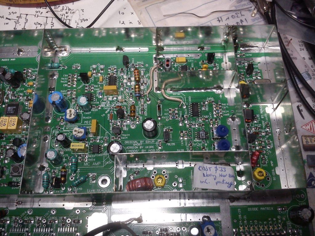
31st Aug, 2011. 'Proto' Version "CC" PCB panels arrived. I had a small number made to check out before any possible future group buys. These are double sided, plated through PCB's with solder resist, component overlays etc.
On the left side taking up about 2/3rd, is the main Combo PCB area which incorporates the Trxavrb controller. On the right side, separated by slots, are the LPF, 20W PA, Encoders8 and Beeper PCB's. They are easily separated from the large panel with side cutters.
This is a Beta version PCB:- >> click for larger size <<


02-Sept, 2011: To make sure all is OK, I am assembling the PCB. After about 4 hours or so, I have loaded most of the DSP section (the LED flashes !) , timer, IF and MR areas.

4th Sept, 2011: Progress is good so far. I now have the IF section working, sensitivity better than -120dBm, all other sections built including the TFT display working (TFT was built some time ago). Only have to fit under PCB co-ax cables and DDS amplifier. {BPF section will come later}
 See and hear Combo C receiving signals ! (2MB
AVI file)
See and hear Combo C receiving signals ! (2MB
AVI file)
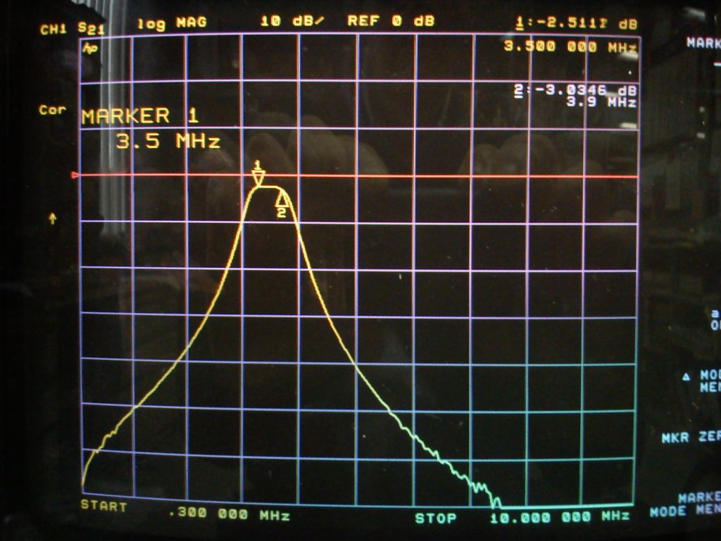
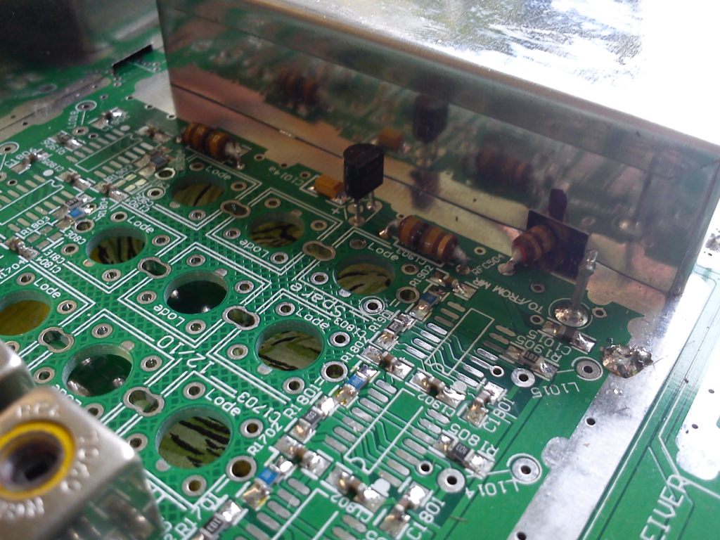
7th Sept, 2011: Receiver is now working ! Listened around on 80M last night. I am experimenting with using an MMIC device in the butler amplifier stage. There is provision to fit one of these devices in place of the 2N3866 stage if you wish. I used a Mini-circuits™ ERA1-SM device. Other similar MMIC's with gain of about 12dB are also suitable. These only require a couple of components to achieve nice flat stable gain. I did some tests to measure output levels over the frequency range with excellent results: +9dBm at 160M and +7.5dBm at 30MHz, measured with an S.A. [ the 'ripple' here is primarily caused by the response of the preceding LPF stage]
Here is a picture of the ERA1-SM amp fitting. NOTE: this is optional in place of the 2N3866 amp. and is a vk3pe 'mod', not supported by the official STAR build. You can see how simple it is ! I also hand wound the 2 coils shown for the DDS filter, using 0.5mm wire on a 4mm drill bit as a former. Normally, toroid cores per Bob's mods, would be used here. (the filter here is wound to Bob's specs. and is a 50 ohm filter. ERA devices are nominally 50 ohm parts so a nice simple fitting) See pdf file here also for full information. (added 29th Dec, 2011)
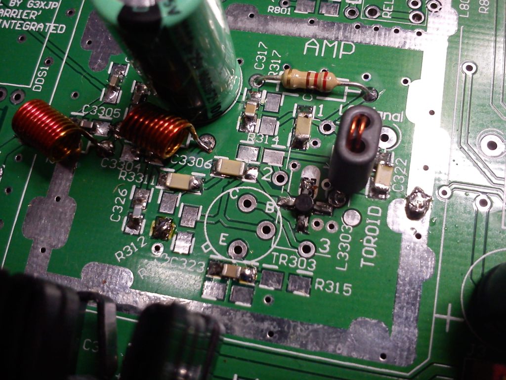 Click for larger picture. (The cap below the 2N3866 is NOT needed.)
12th Sept, 2011: I have now started on the BPF area. The 80M band Toko coils were re-wound and parts fitted. Testing shows about 2.5dB loss. Nice result.
There are Toko winding details on the Combo BB web pages, in the BPF section or HERE. How to re-wind Toko coils is here. A Toko data sheet for standard part numbers is here. There is a company in the UK selling Toko coils. Info soon.
Lodestone formers can also be fitted. Winding information is here, on Paul, M1PVC's build page. Also, Slot-10™ coils can be fitted but they have fairly low "Q" so are not reccomended.
 click for larger picture
To give you a idea of build time, I took about 15 hours to get to this stage. Keep in mind I have built several Picastars, so have some experience !
October 8th, 2011; I am currently testing the Tx side of the radio. I hope to have the Combo star on air on Monday for the local STAR net on 80M. (3.655MHz at 8pm local) Initially with the 20W PA only. <<< see below >>>
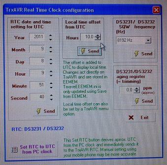
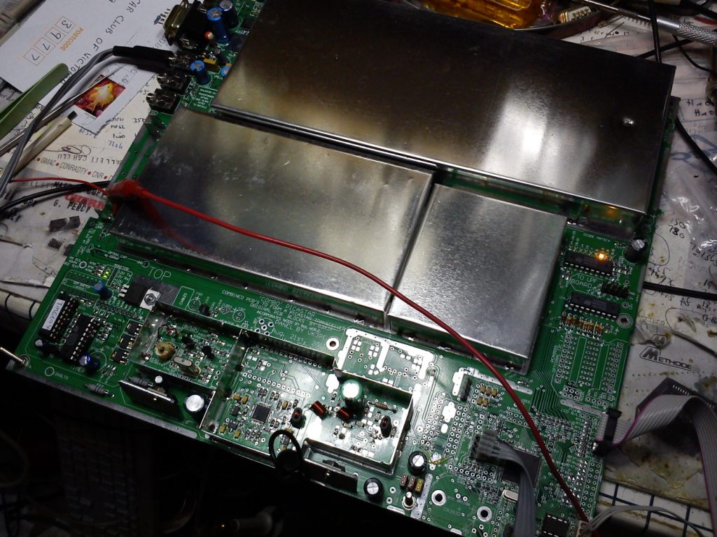
REAL TIME CLOCK (RTC)
There is provision on the Combo C2 PCB, in the Trxavrb area, to fit an RTC. Most of the parts are under the PCB but the battery is fitted on top. I used a surface mount battery (3v) but a holder for a CR2032 type can also be fitted. < some builders have reported poor battery life of the cell and have fitted a re-chargable battery instead. See the Homebrew group posts for more info. >
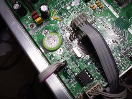
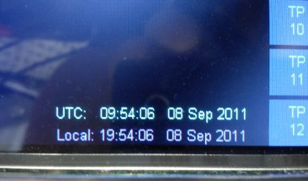
The RTC type and time setting is done using the 'HOBCAT.EXE' program by G3VPX. I used the DS3232 chip. The RTC chip type is set in the 'hardware' menu. Three chip types are catered for. The PCF8563 is NOT catered for.
 The cable in the picture to above left is the USB connection to the PC. Normally,
a USB socket is installed on the PCB or an extender PCB is provided also, to
mount the USB socket in a convenient place on the case.
The cable in the picture to above left is the USB connection to the PC. Normally,
a USB socket is installed on the PCB or an extender PCB is provided also, to
mount the USB socket in a convenient place on the case.
Vers CC is NOW ON THE AIR ! 10th Oct. 2011,
8pm local time, 80M PICASTAR Net (VK) Although not quite finished, I joined the VK Star Net on 80M tonight with 10 Watts. The 140W PA is still to to have a couple of parts fitted. Good reports from all in the Net received.
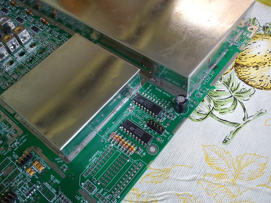
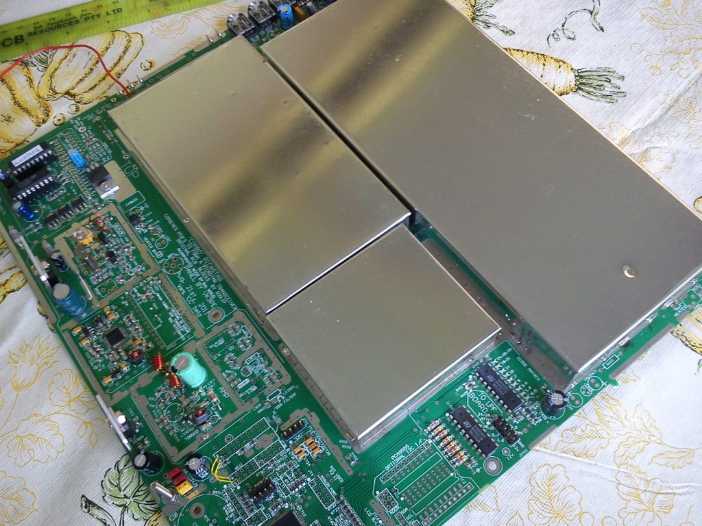
SHIELDING
(Click most pictures below for larger view)
The PCB has provision for extensive shielding. In my case I used tin-plate (from RS-Components™) but other materials like brass can be used also. I carefully cut long strips then formed them to make the walls for each area. Below is a strip method I used for joining and forming a box section. It is important to make the bends at right angles ! Use a carpenters square to make the bend lines.
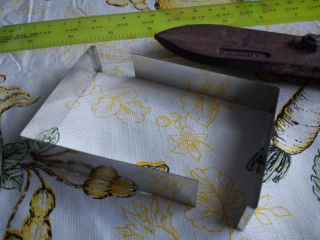
In some areas, the walls must be notched to clear chokes etc. Here is an example of the choke coming out of the MR.
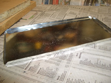
The covers are carefully marked out with a 5mm edge to be folded downwards. I have a small folding machine so this is relatively easy but there are other methods also. See this section on how to make wooden formers to bend the edges. (sample pic is below right) Shielding is a bit fiddly, but take your time with it and it should turn out OK. NOTE:- it is VERY important to place the walls as square as possible. When making the covers, measure the walls once placed on the PCB, for final dimensions ! Don't be tempted to seam solder the walls to the PCB. Just a few solder tacks is enough to hold them in place until covers are made and all testing is completed. It will be very difficult to remove the shields later !. DON'T FIT any shields though until the radio is working.
Only the butler area to be completed now.
The bottom is done in a similar manner but the walls only need to be a few mm high to clear any components or leads.
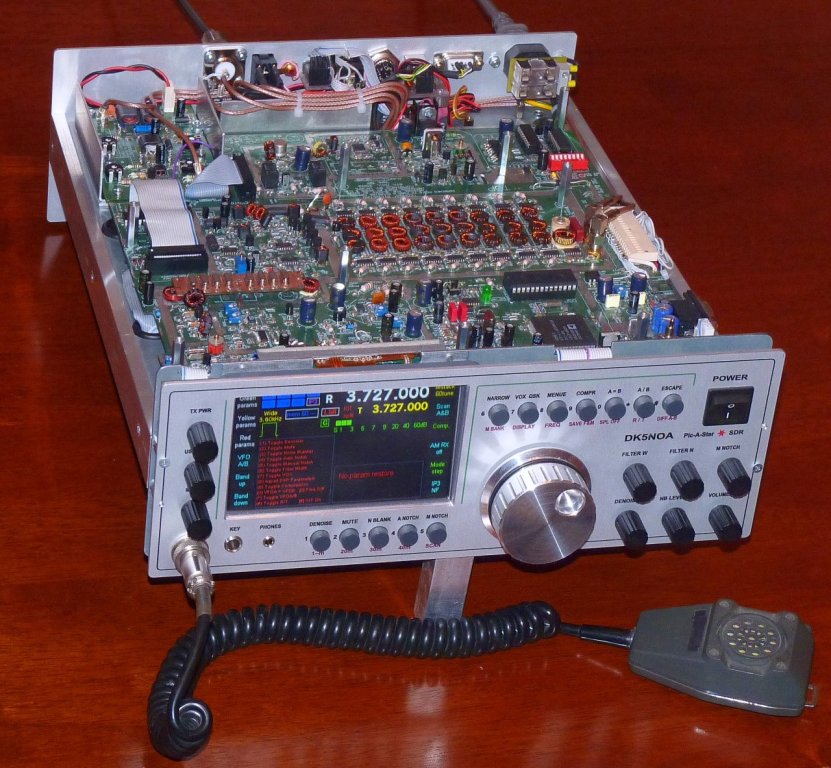
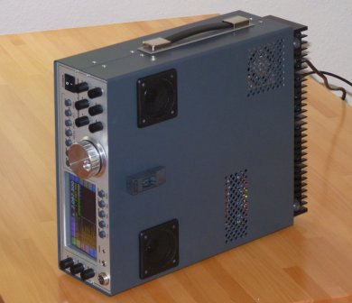
This is an example of how a home made PICaSTAR can look. This one used the COMBO "B" version PCB. A lot of work has gone into this build and is a credit to Enno, DK5NOA.
Click on the left picture to see inside.
VK3PE's build: 29th March, 2012
I am currently working on the housing of my Combo "C" PICaSTAR. I decided this one would be a litle bit special so had a front panel pro made for it, getting a good deal when I visisted a Stand at a Trade show! Panel is black anodised and then engraved. The opening for the TFT has a bevelled edge also around the 4.3" TFT display. The switches mount on 2 home brew PCB's behind the panel. I used Farnell switches, 10mm diameter (Cat # 155-0258). Knobs are from www.altronics.com.au (Cat # H6001) with the 'pointer' ground off. The front panel is 271 x 126mm in size. Case depth 340mm. This is an old instrument case, recycled for this STAR. It will contain a 30A switchmode power supply and 2 loudspeakers, when finished.
By the way, the TFT displays are much better mounted with the cable at the bottom.
 click for larger size.
There are more ideas on building in the Builders pages.
Also, see the link on Combo "B" version pages.
Latest entries:
Cristi, YO3FLR. Very nice job.
Sanyi HA2NJ has updated his modular STAR with Trxavrb and TFT NEW 13th May 2012

UPDATE:- all the group buy Version C PCB's were sold. (latest version is "P2a")
vk3peATbigpond.com
There were 5 PCB's contained in a 'set'. This enables the builder to build a 140W pep output, Combo PICaSTAR.
1) Main Combo "C" Version PCB which includes the Trxavrb control section.
2) 20w PA PCB
3) 140w PA PCB
4) Low pass filter PCB
5) free Beeper PCB for testing.
6) USB 'expansion' PCB to allow panel mount of USB.
You will need to add a display (colour TFT recommended but not mandatory, many other LCD types are catered for) , a 4x4 keypad, tuning and menu encoders and a case. Case can be made from PCB material, a new case (eg 3ru rack case) or a re-cycled one.
BILL of MATERIAL (BOM) main PCB section only at Dec 14th, 2011
NOTE: R629 in I.F. area should be 10k (NOT 10k//5k6) is now corrected in BOM
17th Jan, 2012:- apologies for this, there are a number of resistors in the BPF (3 pages of BPF section) which should be 3k6. Alternate is to fit a parallel 5k6 on top of the existing 10K's if you have fitted them already, or do not have 3k6 values.
Refer to BOM below Vers _4, and new Schematics
Jan 17th, 2012 BOM Issue _4, for "C2" board. There is only a very minor differences to CC above. A 2 pin connector (J10) was added for 12V "out" to the TFT display.
Older version for reference ONLY ! draft BOM for CC Version Issue _3 at Dec 14th,
SCHEMATICS main PCB section only
Jan 17th, 2012:- Updated Schematics for Combo C2 Board includes Trxavrb section
C2a version, use the link above. The only difference is the RTC charger which is here, Charger parts.
The additional parts for the real time clock battery charger option will apear here soon.
Older version for reference ONLY ! Draft Schematics for main Combo "CC" schematics Version "CC", 180811
The "C2", version is updated to the latest values in the BPF area (10k//5k6's) and R629 also 10k//5k6
COMPONENT OVERLAY, BY VALUE OF PART
This pdf is a high definition 'picture' of the main PCB with the component values shown. Use in conjunction with the BOM.
NEW: Jan 17th, 2012:- Updated overlay by value of the COMBO "C2" green or red boards (The C2 & C2a version differs mainly in the area of the DDS amplifier stage.)
If you bring the pdf up on your PC screen and zoom in on the area where you are loading components, you can easily see the values to be fitted.
When mounting the 680nH chokes in the DDS filter, they should be mounted about 3mm off the PCB.
Older for reference only:- This overlay is the prototype only "CC" build. NOTE: R629 in I.F. area should be 10k (NOT 10k//5k6, and values in BPF not correct. See C2 version)
ERRORS ON THE PCB's
the "CC" board:-
The initial Version "CC" PCB was a 'proving' run and there are some errors listed here.
From November, 2011, any future PCB supplied will be final "C2" version.
the "C2" board:-
IMPORTANT--->>> A "C2" error was found, and is detailed here. Dec 15th 2011.
Feb 1st, 2012:- The 1N4148 diode in the Timer area, next to PIC, holes are too small. I cut the leads short and soldered diode on top.
I have found that some C2 (red) PCB's have the overlay shifted or not aligned with all parts. I advised the vendor of this, but it does not affect building of the C2 pcb's. The 'green' boards are not affected.
the "C2a" board:-
May 18th, 2012: The 5v1 Zener diode in the RTC charger needs to be reversed. However, builders report some brands of the SMD Zener are OK. Please check the diode you fit for polarity first.
No other problems known as of May 2012
INTEGRATION DRAWING (how the main pcb connects to other sections)
This is a draft drawing of the interconnections. (14th Sept 2011) It is spread over several pages of a pdf file, which will need to be printed out and stuck together for easy use. It is for an indication only at present, of how the COMBO board is used. More detail will follow later, if requested.
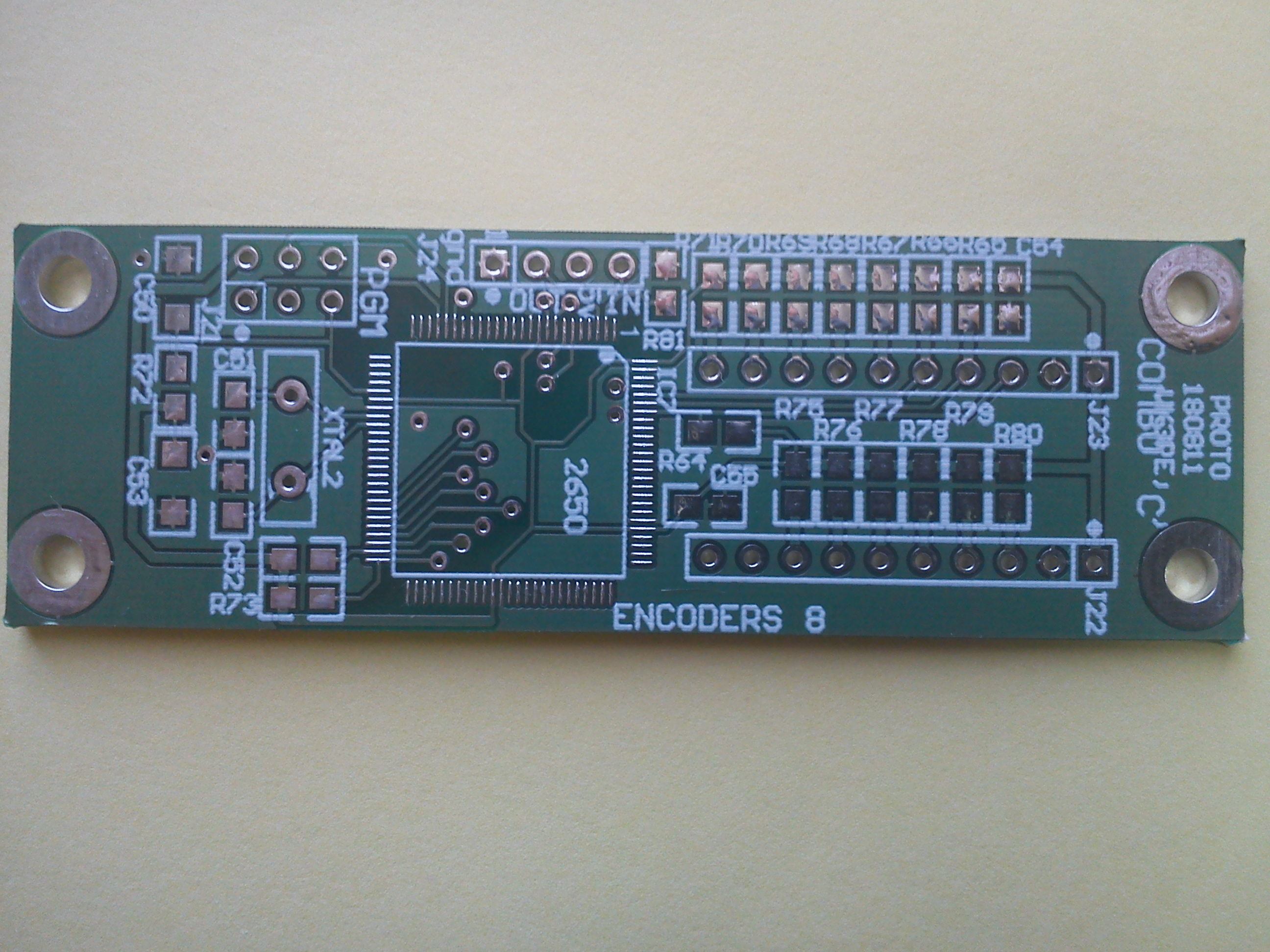
SCHEMATIC & BOM for "Encoders 8" expansion board
This PCB is only required if you do NOT use the TFT_A display board for Encoders 8 function. The TFT_A pcb (available from Gerard, VK3CG) interface has this function built into it.
SCHEMATIC & BOM for 20 & 140W PA's (see G6ALU's web pages)
PLEASE NOTE ! the values of R13, R14 & R15 are shown INCORRECTLY on some of the 140W PCB's overlay. Please use the link above to get the correct values. On "C2" red Panels, the value is not shown.
** To keep 140W PA PCB costs down, you will have to file out the holes for the PA transistors yourself. Use a round file after drilling a pilot hole. The 20W PA PCB will also need to be trimmed to length. There is a section of pcb at the end which can be cutoff.
The original SD1487 transistors are now impossible to get. Other devices though can be used. (see my Combo B version web pages)
SCHEMATIC & BOM for LPF (see G6ALU's web pages)
Beeper board.
BOM kindly supplied by Bill, N4BKT, 31st Dec 2009
This section of the Combo C2 board is included in the BOM for the main PCB. You need to refer to G3VPX's web pages for full info on programming (including the software) of the Trxavrb and Encoders8 section. Also, the TFT display.
See here:- G3VPX's TrxAVR Interface web pages.
Winding Trifilar Balun 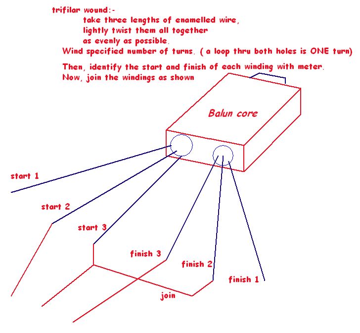
CHOICE of DISPLAY
PICASTAR originally used 6 x 7 segment LED displays. Later, Ian, G3VPX, developed a new controller, called TrxAVR. This controller is integrated onto Combo C and allows the use of more modern displays using LCD's and later, also catered for a full colour TFT display, designed by Chris Stake with software by VK3CG. To use the TFT display, a separate PCB, (not provided with COMBO) is required. TFTA PCB's and in fact, a kit of parts is available from VK3CG. The actual TFT display can be bought in either 4.3" or 5" sizes on eBay and other on-line stores, very cheaply. Touch screen types are also catered for in the design.
TFT DISPLAY
There is some information here on setting up, and programming the TFT PCB if you are fitting a TFT display.
NOTE: some displays are better mounted with the ribbon cable at the bottom. Check yours before final fitting into case.
NOTE ! This PCB was prepared in good faith as a labour of love. Although carefully checked and preceded by the B version, errors can occur in design and also in the PCB making process.
The PCB is based very closely on the original PICASTAR PCB modules designed by Peter, G3XJP, who designed the PICASTAR transceiver. The RSGB's RADCOM magazine contained the original articles on construction. Those articles also appeared in the RSGB's Handbook but neither should be used as the basis for building a PICASTAR as the design progressed over the later years.
This COMBO version is the COMBinatiOn of those modules into one large PCB, to ease construction. G3XJP recommends the building of PICASTAR using the 'self-learning' approach of doing as much as possible ones self. ie making PCB etc also. Full PCB designs of that method are included in the 'picaproject' group for those who wish to follow the original philosophy.
The COMBO versions include all later changes made to the original design per the official modification list contained in the picaproject group.
You need to be a member of the Yahoo™ 'picaproject' Group for access to the latest files and software. You need to join this group and digest all the information contained there on the project and especially the set-up information. It is also very helpful to be a member of the 'homebrew-radios' and 'picastar users' groups. Refer to those groups for information on joining. If you wish to fit the colour display, there is a TFT_A Yahoo group also.
PCB's will only be available to members of the picaproject group.
In the UK, there is a homebrew NET on 3.727MHz which often discusses PICASTAR, I believe.
In VK, 3.655MHz at 8pm EAST on Mondays is a NET dedicated to PICASTAR builders.
page by vk3pe, August 2011