 the single board
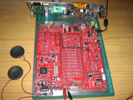
Combo PIC-a-STAR PCB's
This page last updated on July 31, 2022 updating this new page for P1 and now P2, P2a version.
click this picture
the single board
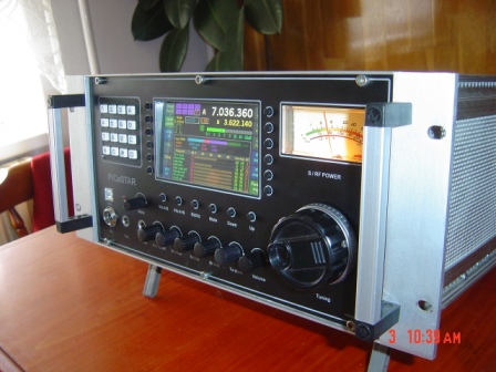
PICASTAR is an all band HF Ham SSB & CW transceiver designed by G3XJP and originally appeared in the RSGB publications, "Radcom" and year Handbook.
It has been a very popular home build Rig for Amateurs the world over, with hundreds having been built and even after a number of years, still atracting interest from home builders the world over. G3XJP published PICASTAR as a home brew project, including making of PCB's at home. For some this proved an obstacle and later, VK3PE produced some PCB's closely based on G3XJP's original modules, to make the build easier for those who chose to go this way. Boards were only supplied to order in group buys.
This is not to say building PICASTAR
is simple. It is NOT a kit. Nobody supplies a set of parts for this project.
It is up to the builder to buy all parts themselves. However, like the PCB's
from VK3PE, there have been a number of group buys of parts to keep costs down
or to supply parts that might be a little harder to find. Being a member of
the Yahoo "picastar-users" and "homebrew-radio" (EDIT July 2022: see now https:groups.io/g/homebrew-radios) is also
very handy. Building a PICASTAR though requires a builder with at least some
experience of parts assembly and set up, testing etc.
The original information and software
for the DSP and PIC's is contained in a Yahoo "picaproject" group.
You MUST be a member of this to build Picastar. If not, you will lack the software
and original build and set-up information ( or "manual") If you wish
to make your own PCB's per the original design, PCB information is also contained
within this group.
A case for the finished Rig is also up to the builder. The original idea was to use PCB material to make a case and this can work very well. Others have adapted old commercial cases to house their "PICaSTAR". This is a great way to get a "pro" case but one can also be made from aluminium extrusions with a little effort for a very nice result.
What is this "Combo" project page about ?
"COMBO" PICaSTAR
The Combo version integrates most of the original G3XJP module system PICASTAR into a single PCB. The idea behind this was to simplify the inter-wiring by having most of it as part of the one PCB, connecting the various functional blocks of PICASTAR. This means that a PICASTAR can easily be built and got going, without having to do extensive wiring.
There have been several versions of the "Combo" pcb versions of PICASTAR.
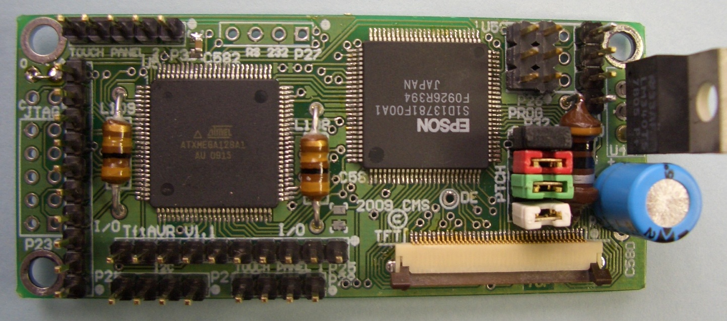
In order to prove the idea, VK3PE originally designed the "AA" version. Only a few were made, to prove the concept by building and testing. Later, as some bugs were found and other improvements added, other versions were made, being the BB, C2 and C2a versions. The original "AA" version used PICnMIX controller but when Ian, G3VPX, developed the Trxavrb controller, this was then added to the Combo also. Trxavrb allows the use of various numeric LCD and graphical displays upto a full colour TFT display in either 4.3 or 5" sizes.
This web page was created on July 19th, 2012 and will try to reduce any confusion for potential builders of these boards, by separating out the various versions, into new web pages.
Where the information covers all of the versions, it will remain on this page. Also, there are links here to builders of the boards to show the various ways that the PICASTAR can be built.
Availability of PCB's July 2022: no Group buys available now.
Work has been completed on a new development. I have called it "Porta-STAR" and is designated Version "P1" This is very similar to the Combo versions, but the board is split so that each PCB half fits either side of a central chassis. Overall footprint size is then much reduced and is aimed at those who have enquired about a version more suited to mobile or portable use. Each half is then interconnected with a single, short, 20 way IDC cable. Some of the previous co-ax cables have been removed also. See links below.
This board set was available in early Jan 2013 as a group buy only, to Yahoo homebrew-users group members. In May, 2013, a slightly updated version, "P2" was released for a Group buy.
UPDATE: 23rd Nov, 2014,
There might be a spare Combo P1 or P2/a board set, contact VK3PE. Please refer
to this page for details
of the P1 and new P2/a version.
vk3peATbigpond.com
 << click picture for larger size. This is not
the latest P2 version.
<< click picture for larger size. This is not
the latest P2 version.
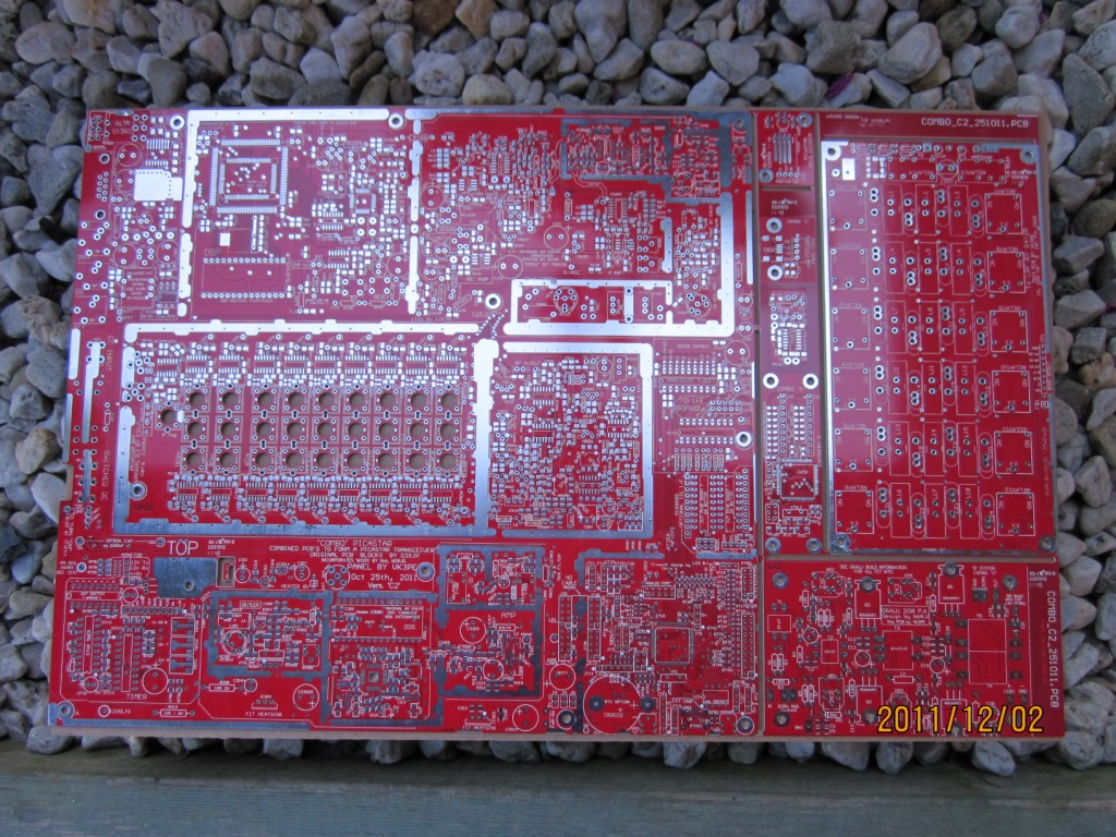
Above:- This is the version C2 or C2a type panel of PCB's. The left 2/3rds is the main Combo board. To the right is the 20W PA, LPF and some smaller pcb's like beeper which are easily removed with sidecutters. Previous versions are similar. The panel is about 410mm wide and 260mm high. The 140W PA pcb is not shown here.
Bill of Materials etc Click version link below:-
Version "AA" Only a few boards were made to test the concept and used the original G3XJP "PICnMIX" (7 segment LED display) controller.
Version "BB" This version added the Trxavrb controller as a separate PCB, connected by ribbon cables to the main PCB
Version "C2" The Traxavrb controller is now integrated into the main board to further reduce wiring, along with a real time clock option.
Version "C2a" Same as the "C2" version except a battery charger option was added for the clock back-up battery. See here for RTC info.
NOTE:- Versions "C2" and "C2a" also allowed the use of some modifications by M0RJD, to the original circuitry, to improve performance in some areas.
The modifications are described by M0RJD on Bob's web pages.
Version "P1" Dec 2012 NEW version that splits the Combo into two PCB's to allow a smaller footprint rig to be built.
Version "P2& P2a" May 2013 NEW is a slightly updated version of the P1. (some minor pcb errors fixed)
This in an Excel version of the P1 and P2 BOM.
This P1 & P2 BOM shows the QTY of each item and is a text file only. Note, there are a number of options and alternate parts fitting to allow for available parts etc.
Please refer to this page for more details of the new P1 version.
Schematics
Version "BB"
Version "P1, P2& P2a" --->> Please refer to this page for "P2 & P2a" version.
COMPONENT OVERLAY, BY VALUE OF PART
This pdf is a high definition 'picture' of the main PCB with the component values shown. Use in conjunction with the BOM for loading the board.
If you bring the pdf up on your PC screen and zoom in on the area where you are loading components, you can easily see the values to be fitted. Normally, one would fit the most common parts first. eg 100nF caps as there are about 150 of them in the project. Then, say, the 10k resistors and so on.
When mounting the 680nH chokes in the DDS filter, they should be mounted about 3mm off the PCB.
Version "CC" build. NOTE: R629 in I.F. area should be 10k (NOT 10k//5k6, and values in BPF not correct. See C2 version)
COMBO "C2" & C2a (The C2 & C2a version differs mainly in the area of the DDS amplifier stage.)
Version "P1" build notes Please refer to this page for more details of the new P1 version. Also covers the "P2 & P2a " versions.
ERRORS ON THE PCB's
"CC" board:-The initial Version "CC" PCB was a 'proving' run and there are some errors listed here.
"C2" board:- A "C2" error was found, and is detailed here. Dec 15th 2011. and Feb 1st, 2012:- The 1N4148 diode in the Timer area, next to PIC, holes are too small. VK3PE cut the leads short and soldered diode on top.
I have found that some C2 (red) PCB's have the overlay shifted or not aligned with all parts. I advised the vendor of this, but it does not affect building of the C2 pcb's although in some cases, some scraping of the overlay might be needed. The 'green' boards are not affected.
"C2a" board:- May 18th, 2012: The 5v1 Zener diode in the RTC charger needs to be reversed. However, builders report some brands of the SMD Zener are OK. Please check the diode data for polarity first.
No other problems known as of May 2012
Version "P1" A few small problems. Please refer to this page for more details of the new P1 version.
Aug 14th, 2013: Pin 16 of connector "JT6" in the Trxavr area, is not connected to ground. This only affects those using an LCD display and can be overcome by using the ground connection on pin 1 instead.
Version "P2" (P2 is the P1 version with above errors corrected)
Aug 14th, 2013: Pin 16 of connector "JT6" in the Trxavr area, is not connected to ground. This only affects those using an LCD display and can be overcome by using the ground connection on pin 1 instead.
Version "P2a" (P2a is the P2 version, slightly updated) No known errors.
Other PCB's
Each of the versions above was supplied as a "panel" containing the main "Combo" plus several PCBs which are easily be removed for power amplifier and low pass filter areas. These are 'modules' but were not part of the original PICASTAR project as no power amps were included.
There is a 20W PA and a 140W PA PCB. The 20W can be used alone or can drive the 140W PA. Details of the PA's and LPF are found on the G6ALU web pages.
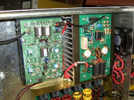 20w and 140W PA's with LPF just below.
Suggested sequence of building the Combo PICASTAR
This link shows a suggested way to build and test your new PICASTAR in easy steps. Testing as you go!
Integration
To wire up your Combo STAR, you can refer to these drawings which should simplify the task somewhat. Click on the version in the next line for details:-
Integration drawings for Versions AA, BB, and the C2 and C2a. For Version "P1, P2 & P2a" see here.
Displays
The Trxavrb controller is integrated into the "C2a" version and can be used with:-
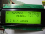
2 x 16 character LCD modules commonly available at low cost.
128 x 64 LCD graphic modules which are cheap and effective.
320 x 128 LCD graphics modules are larger of course.
You can always change to a different display type later, as you wish.
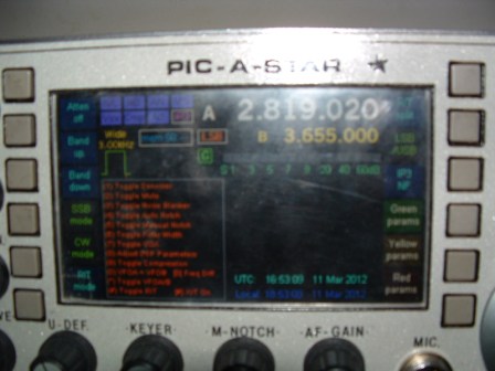
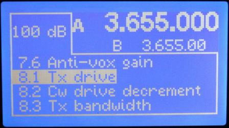
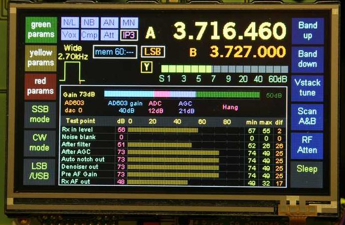
Colour TFT display. This is the 'ultimate' display for your STAR build ! It requires a TFT display easily found on eBay for about $30 in either 4.3" or 5" types. Including a touch screen which can also be used on the project. Very BLING and a feature not found on any other home brew rig I am aware of. You can of course build with the simpler displays and "upgrade" later to the TFT type. However, it does require the purchase of a small additional PCB called the "TFT_A" which connects to the I2C port on the Trxavrb controller. This TFT pcb was not available from VK3PE, but must be purchased from VK3GRS. Some parts might also be available for it from VK3GRS, although not guaranteed.

No display ! The Trxavrb can also be used to remotely control PICASTAR using G3VPX's "Hobcat" program running on a PC using a USB connection.
G3VPX's "Hobcat" program is also required to setup the Trxavrb control section of PICASTAR. Hobcat allows one to "hardware" configure your PICASTAR. Things like display type, front panel switches and rotary assignable encoders etc. It also allows one to load the DSP code and parameter files. Assignment of the touchscreen buttons (TFT only) is done through the PICASTAR front panel "Menu" encoder. Details are in G3VPX's web pages. There are many paramaters and operating setups that can be configured with this radio. Refer to the above link for more information. Be prepared for some sensory overload as the options are many !
Front panel
The front panel controls can be fitted acording to the builders wishes. Minimum is a tuning control and Menu encoder. The menu encoder is used to slect and adjust various parameters, at will. A 4x3 or a 4x4 keypad is also normally fitted and through this, parmaters can also be changed and allows DSP and DDS chnages quickly.
Real Time Clock (RTC)
The PICASTAR project (with Trxavrb controller) allows the optional fitting of a RTC display. This is integrated into the latest boards and also includes a charger for an external Ni-Cad or similar re-chargable battery pack. The time and date, local and UTC then appear on the display. Only a few compoments are require for the RTC. It can be fitted later if required.
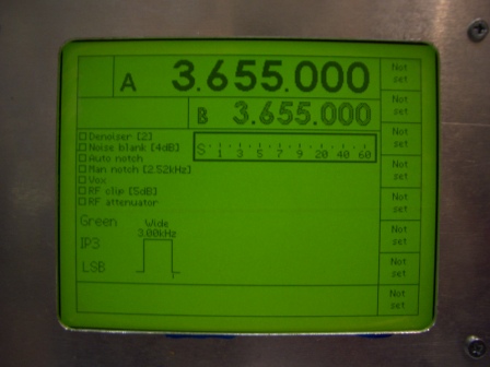
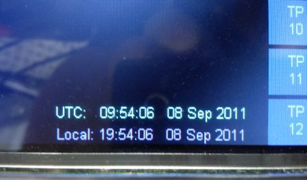 The "TP" sections on the right of the screen are assignable touch
screen buttons. There are a number of possible sues, like band up/down, SSB/CW,
DSP bandwidth and many more than can be used. Once assigned, the "TP"
designation is then changed also eg "SSB", "CW" etc.
The "TP" sections on the right of the screen are assignable touch
screen buttons. There are a number of possible sues, like band up/down, SSB/CW,
DSP bandwidth and many more than can be used. Once assigned, the "TP"
designation is then changed also eg "SSB", "CW" etc.
Shielding
Like all RF projects, good shielding is essential for best results. However, with the Combo, the radio can be built up and tested, even put on air, without much initial shielding. Then when happy with the build, fit the shielding last of all. Some tips on making shields is given here.
Builders pages
To get some additional ideas or just to see how others have built PICASTAR, see the builders pages below. When you are building your own STAR, you can have yours featured here also.
STAR BUILDERS PAGES April 2012 UNDER CONSTRUCTION
More STAR BUILDERS April 2012 UNDER CONSTRUCTION
.jpg) Steve, G7WAS, PICASTAR using the module PCB's.
NEW July 31st, 2012
Steve, G7WAS, PICASTAR using the module PCB's.
NEW July 31st, 2012
Click picture to see more of Steve's nice work.
Beeper board
A simple test board for low voltage testing of continuity is included on most versions of the Combo PCB panels. It is a good idea to build this first, as an introduction to SMD parts if you are not familiar with them. Don't be put off though by SMD parts, they are easier than through hole !
Beeper board information.
BOM kindly supplied by Bill, N4BKT, 31st Dec 2009
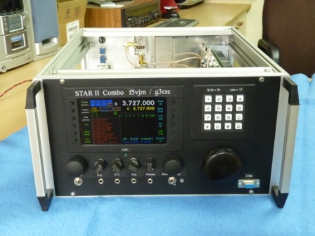
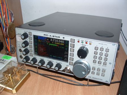
Some typical PICASTARS
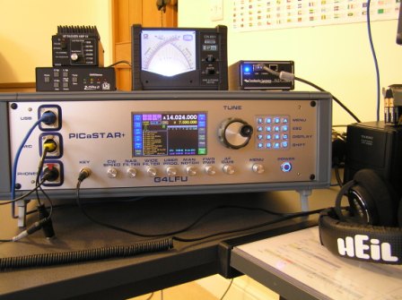
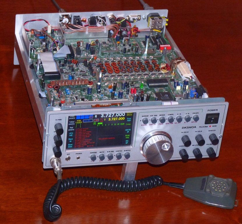
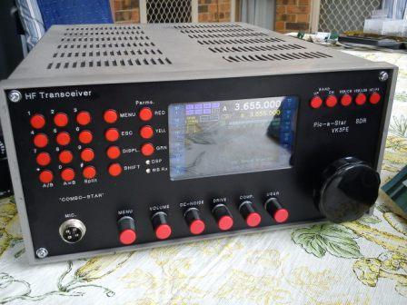
DK5NOA's PICASTAR above was built using a homemade case.
This PICASTAR is built using the traditional PCB
material case.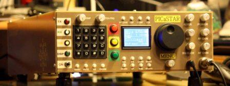
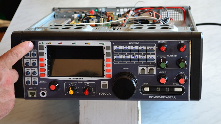 YO5OCA's fine build
 One of VK3PE's many builds.
This page created on 19th July, 2012 © VK3PE
No guarantees are given or implied as to the suitability of this material for any purpose whatsoever.
. Any inadvertant use of Trademarks is accidental and not an endorsement or otherwise of a product.