"Porta-Combo"
Version "P1" & "P2/P2a", PICaSTAR
IMPORTANT:-
You MUST be a member of the Yahoo™ 'picaproject'
Group for access to the latest files and software
and to purchase these PCB's in the group buys. You need to join this group and
digest all the information contained there on the project and especially the
set-up information. Picastar was designed by Peter, G3XJP, who wrote a series
of articles which appeared in RADCOM magazine and also RSGB handbook, 2006 edition.
You need,
at the very least, to have read through these articles, for the backgound information,
setup procedures and design details. In addition, information on coil and transformer
winding is contained in those articles, that are now duplicated on the PICAPROJECT
Yahoo Group pages. PICAPROJECT
is not active as a reflector, it
only contains files.
Carlos,
EA1CGK's, magnificent build. JULY
2017
| Jan 25th, 2015:
Panadapter. page has been updated
with more on the colour TFT version by Mats. |
NEW March 20th, 2015:
For those struggling to find the 2nd LO crystal, which is a custom made
part, Terry, VK5TM, has developed a 20 x 30mm PCB to fit in the area of
the crystal oscillator to provide either 10.710 or 10.715MHz output, selected
by a simple link. It uses an Si5351 and PIC. Terry can supply the blank
PCB and PIC already programmed. VK5TM
STAR Local Oscillator Module for full info. Picture
below.
Contact Terry directly please.... >>
see QRZ.COM for email address.
|
| |
NEW Jan 25th 2015:
'P1' Build now on air ! Tony,
G4CIZ Pascal VK2IHL
has done a nice job on his build. |
| |
NEW Sept 2015, Aurel has finished his 2nd
STAR, this time with a Pandapter display also See builders pictures near
end of this page. |
| |
|
| |
|
| |
|
NEW 1st
Nov 2015 overlay link fixed.
NEW
Jan 25th, 2015: For those struggling to find
the 2nd LO crystal, which is a custom made part, Terry, VK5TM, has developed
a 20 x 30mm PCB to fit in the area of the crystal oscillator to provide either
10.710 or 10.715MHz output, selected by a simple link. It uses an Si5351 and
PIC. Terry can supply the blank PCB and PIC already programmed. VK5TM
STAR Local Oscillator Module for full info. Contact
Terry directly please.... >> see QRZ.COM (VK5TM) for email address.
_170315%20001.jpg) March 20th 2015:-
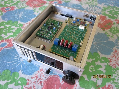
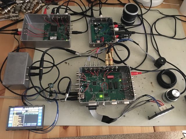
Here is Terry's 2nd LO PCB installed in VK3PE's Picastar, for testing. It would
normally be fitted in the 2nd LO compartment to the left. In this case it was
soldered to the walls of the Mixer area just for the purpose of testing as the
crystal oscillator was already present.. Obviously, a top cover would also be
fitted on the compartment also. Terry's module would be
powered from the 10V supply rail in the crystal oscillator position, using the
existing 100uH choke feed. No ill effects were observed using the Si5351 based
crystal substitute, but vk3pe was unable to perform any actual measurements
to see if there are any unintended problems.. Contact
Terry, VK5TM, via QRZ.COM for more information on PCB availability.
March 20th 2015:-
Here is Terry's 2nd LO PCB installed in VK3PE's Picastar, for testing. It would
normally be fitted in the 2nd LO compartment to the left. In this case it was
soldered to the walls of the Mixer area just for the purpose of testing as the
crystal oscillator was already present.. Obviously, a top cover would also be
fitted on the compartment also. Terry's module would be
powered from the 10V supply rail in the crystal oscillator position, using the
existing 100uH choke feed. No ill effects were observed using the Si5351 based
crystal substitute, but vk3pe was unable to perform any actual measurements
to see if there are any unintended problems.. Contact
Terry, VK5TM, via QRZ.COM for more information on PCB availability.
Jan 25th, 2015: Panadapter.
page has been updated with more on the colour TFT version by Mats.
Dec 27th 2014
R517 in MR area of schematic should be 2k2 in parallel with
1k2
Other
PCB's.
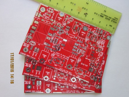
Some experimental versions for extending
response to 6m. Uses an MMIC as input device and different ferrite materials.
Only a few available. I have NO original 20W pcb's.
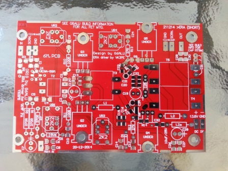
These PCB's are a little shorter than
the original G6ALU boards and use an ERA-5 (MMIC) in the first stage. The FET
mounting holes are in the same position as the G6ALU pcb though. They are for
experimenters to extend the range to 6m and maybe a little more. I have built
one using 61 mix ferrites and the 'VHF' versions of the output FETS. Unfortunately,
at present, I don't have all the details and test results due to some PC problems.
One could build with the specified G6ALU parts and ERA-5 though, also.
March 20th,
2015:- Experimental
schematic is here. No further information is available at this time.
Jan
8th, 2014 Wiring diagram for various
displays added.
7th
Dec, 2013: clarify RS232 adapter cable. See
Schematics.
Please check
here as you build, to see if any issues with the PCB's.
29th Nov,
2013: VK3ATC , VK3PE & F1CHM have been experimenting
with a DSP based Panadapter
Update: 4th Jan,
2015, Mats
SM0RJV has also done a lot of work
using a colour screen.
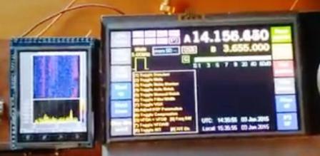 YouTube screen shot.
 TONY, G4LFU's P1 STAR BUILD (CLICK FOR DETAILS) Oct
2013
TONY, G4LFU's P1 STAR BUILD (CLICK FOR DETAILS) Oct
2013
**
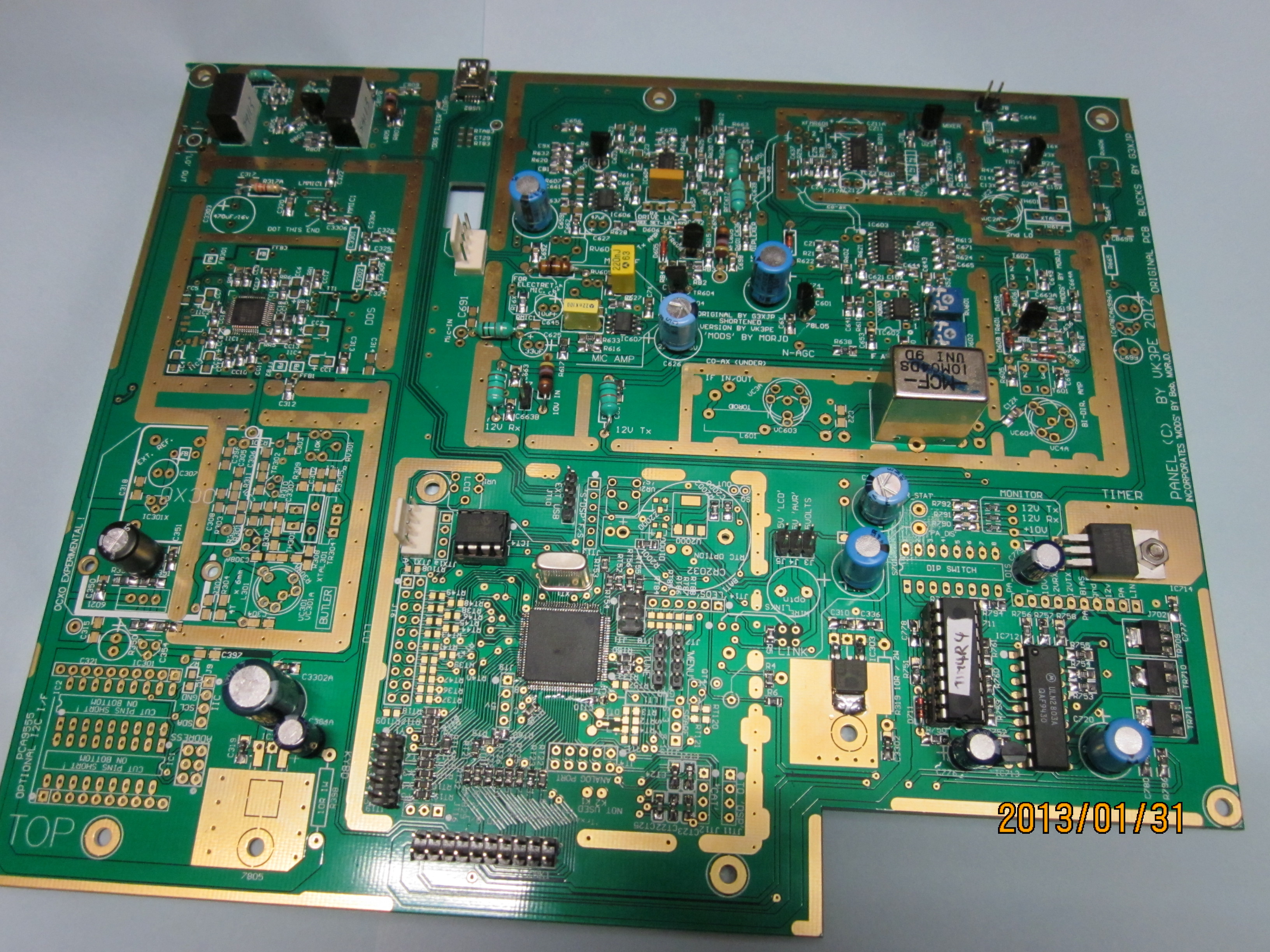
All pictures below show the "P1" version PCB.
But, "P2 & P2a" are near identical.
25th July
2013: the overlay drawing has been
corrected (bottom side, top 3 bands had missing parts text)
24th Aug 2013:- New builder added
! Tony,
G4LFU
16th Aug 2013: For sale !!! P2 PCB set including
DSP and AF section loaded and tested, See
this page for details.
NOW SOLD
10th
May, 2013 Toroidal BPF PCB's
A few spares still available from a group buy.
6th May 2013,
new P1 on the air, see builders section.
March 27th, May 6th,
builders section updated. Four P1's are now on air !
** March 21st, Z2000
in the RTC charger clarified (see errors, BOM and Schematic
areas this page)
March
11th, Integration drawing
has been updated.
11th March, 2013 F1CHM,
AC6AO and 4Z7LES
builders pictures added.
*** 5th March, 2013:
there is a missing ground
on IC1604, pin 7 in the BPF area. "P1" only. (thanks Dan) ***
3rd March, 2013, pictures
of cabling and VK3PE's build added in integration section.
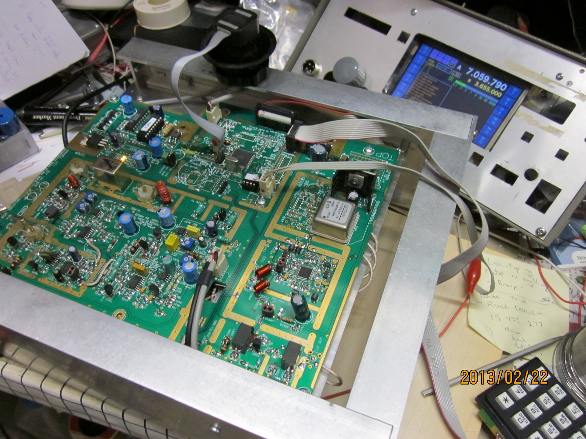
Feb 22nd, 2013:- VK3PE's
Combo P1 is now receiving signals ! See and hear it also
here.
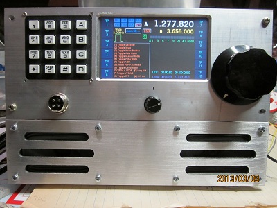
Feb 17th 2013: The
OCXO and DDS in x4 mode is now working correctly ! (Thanks
Ian for s/w fix) The Home made case is progressing well
also.
As detailed in this web page, use of the suggested OCXO is EXPERIMENTAL.
VK3PE now has new Trxavr software from Ian, G3VPX, running correctly in the
DDS in x4 mode. The new version is Version 1.73 (Previous versions did NOT
work correctly in multiply mode.) NOTE:- Phase
noise will be degraded in 'x4' mode.
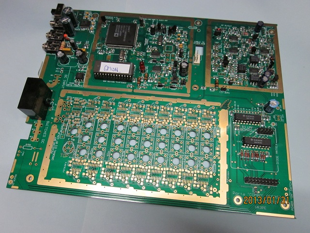

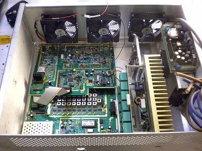
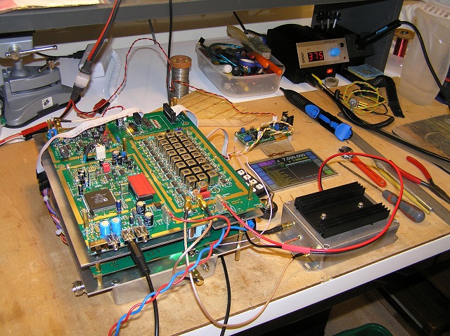
See above. (Click for larger picture)
Not all parts are fitted. This is the result of about 12-14 hours of assembly
so far. Having built a few Combo's, most parts are from extra's I bought previously.
Tomorrow I will order the few parts I don't have. This build will be with the
experimental OCXO in place of the Butler. It is not yet fitted in these pictures.
The build will be tested with a TFTA PCB display already built up before. Plenty
of coil winding to be done, a tedious part of the build.
I have powered up the DSP section
and yes, the LED flashes !
Pictures may not be in focus !
This
page may have links to other www.carnut pages.
Please use the BACK key to return from those pages. (these
are NOT fancy web pages !)
This is a variation on the previous single board
versions called 'Combo" to build a PICaSTAR transceiver. PICASTAR was originally
designed by G3XJP and the Combo versions use essentially the same module layout
as the original, but combined to reduce wiring and ease assembly, by vk3pe.
NOTE: there is NO
kit available for the PICASTAR project! The PCB's are usually made available
as a limited group buy only. You need to have some experience in home brew of
Amateur radio equipment although any keen Amateur is probably capable of building
this multi-band HF (SSB/CW) rig. There are many facets to the build, you will
need to purchase all parts yourself. A few parts are slightly difficult to obtain
but not impossible by any means. You need to be able to fit or willing to learn,
mounting some surface mount components. Some PC knowledge is handy also as you
need to program the DSP code into the radio etc. Much friendly help is at hand
though, if you join the Yahoo 'picastar-users' and 'homebrew-radio' groups.
To obtain the software, you MUST also be a member of the Yahoo 'picaprojects'
group.
There are also a number of ways to build and house
the project, with some exciting display options available, from simple LCD through
graphic types up to a full colour touch screen TFT display, either 4.3"
or 5" in size. If you wish to fit a colour TFT display, then a TFT_A PCB
is required, which is available only from VK3CG.
PICASTAR can be a very impressive radio to look
at, depending on your skill level and facilities, or you can build it as simply
as you wish. Performance is excellent for a home brew rig and there are many
happy builders all around the world. If you wish, you can also build PICASTAR
to the original design by G3XJP, including home etching of all the PCB's. All
artwork, software and documentation is available on the Yahoo "picaproject"
group. (This is not a discussion group, just a depository for G3XJP's many clever
projects.)
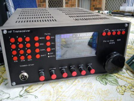
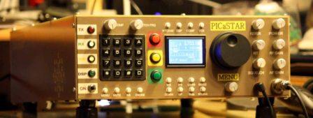
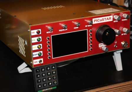
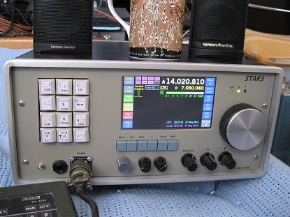
Below is an example of a Combo PICASTAR, with 4.3"
TFT display. It is not a P1 version build. The picture does not do the
display justice, due to reflections. A version built with these newer 'Porta'
boards is capable of being built smaller than this one although much will depend
on what front panel options are used.
 More pictures here
The "Porta" version is a repackaged Combo
version that splits the previous single Combo PCB into two, to allow the building
of a smaller footprint rig. The two boards are almost identical in size (about
9.1 x 7.1") and the idea is to mount them either side of a central chassis.
The two boards are connected with a ribbon cable and some coax cables. The PA
boards and Low Pass Filter boards are separate and as before.
Here is a pdf 'picture' from the PCB design to give
an idea of the two boards. It can be printed out life-size. Side
1, side
2:- Either board can be mounted on top but it is suggested that the one
with the BPF section be the top board. This 'picture' is taken from the PCB
program and may vary a little, in the final board.
The paper printout shows the size compared to the
older single board version. Of course, there are two of these boards now, suggested
is to mount one on either side of a central chassis. NEW
Jan 9th 2013
The boards are in two "panels".
Once received by you, the boards can easily be separated out of the panels
with a sharp pair of side cutters or a fine bladed saw. In some cases, you
will also need to trim a little off some of the boards as you can see in the
picture above. Use a fine bladed saw or cutters, then smooth with a small
flat file.
SCHEMATIC:
>>> covers P1, P2 & P2a versions
with a page of explanations
included.
UPDATED 27-12-2014:
R517
is now 2k2 in parallel with 1k2.,
(was 2k2.)
RS232
cable details added. This cable unfortunately is
different to that used by G3XJP on the homebrew PCB's. So, if you built H/B
pcb's and made up a cable for the RS232, it is different on P versions. Sorry.
Details are in the Schematic file (link above) and also here, in
this drawing.
The schematic is essentially identical to the previous
Combo versions of PICASTAR. It may include some options as the board can be
built with some variations. See the next two paragraphs also please.
In the real time clock
area, Z2000 zener diode may be reversed on the PCB, depending upon the
brand and type you may buy. The correct Zener type is a BZX84-C5v1 or
a BZX84-B5v1. If you have the 'reversed' type, you will need to rotate it
on the pads until the correct connections are made. (If the diode is incorrect,
there will only be about 700mV available at the output.)
The RS232 mode switch
requires the fitting of a 1k resistor, across the active pins, to allow the
S meter etc to operate. The simplest way to do this is to fit a leaded resistor
under the PCB across the RS232 jack switched pins. See Schematic link above
which has RS232 test cable details also. (Dec 2013)
17th May 2013:
On the P2 and P2a version PCB, this 1k resistor
is now mounted under the PCB, on the RS232 jack and is auto switched in and
out.
Schematics, BOM etc for the PA's and LPF are not
generally shown here. Refer to previous pages and G6ALU
web site, for this information.
NEW Jan 2016:
I have some information here
which also shows plots of each filter.
Bill
of Material (BOM)
<<<--- Note: the BOM does NOT
include the PA's, LPF, USB extender and Beeper PCB's. Or the TFTA.
8th Jan 2015:
Current Bill of Material (BOM)
for P1, P2 & P2a etc
Jan 25th, 2015:
For those struggling to find the 2nd LO crystal,
which is a custom made part, Terry,
VK5TM may have the answer for you. Terry has developed a 20 x 30mm PCB
to fit in the area of the crystal oscillator to provide either 10.710 or 10.715MHz
output, selected by a simple link. Contact Terry via QRZ.com
This BOM text file shows the QTY
of each item and is a text file only. > UPDATED
17th Dec, 2014 Use in conjunction with the Excel file above, please
for details.
NOTES !
Feb 17th:-
C320 is better NOT fitted, in the ERA-1 area. Slightly more output and flatter
response. I will update the BOM soon.
Jan 6th, NOTE:-
C20x value in the 2nd LO is shown as 47pF. VK3PE found that a lower value is
required so that the crystal can be set to exact frequency. e.g. 18pF.
The
BOM shows every part on the VK3PE STAR Schematics. BUT,
not all parts are actually required, as it depends on various options and alternate
part provision on the PCB's.
Note, there are a
number of options and alternate parts fitting to allow for available footprint
and parts etc. Generally, (except in the BPF section) a ref number ending in
"A" is an Alternate part that can be used.
Parts
for the PA's and LPF are not in the above BOM. You need to refer to the G6ALU
web pages for those BOM's.
READ THIS, it also helps on parts
supply sources.
Notes
for building this version (.doc file) Information on parts, how to
build etc. pdf
version
Component
overlay by Value of parts.
Use this for quicker assembly of the PCB's.
18th Feb 2015
P1,
P2, P2a overlay R525 & R526 are Not Fitted. (NF)
PLEASE NOTE >
LED's in the matrix area are shown incorrectly on the "P1"
PCB only. For the P2 & P2a version PCB, this has
been corrected and the P2/a PCB overlay link above is OK.
PA's,
LPF etc Please use in conjunction with the G6ALU web
page information. G6ALU's
web pages
Problems
with the "P1" & "P2/a" PCB's?
If problems are found, updates will be posted
in this section.
NOTE:-
all of the PCB's are electrically tested [E-Test] by the PCB vendor (at extra
cost) but is NOT a guarantee that there may not be a sliver of unetched copper
shorting a track or pad, on an occasional PCB.
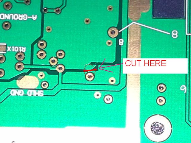
P1 version:-
Jan 31st;
there is a small sliver of copper shorting some tracks. It's on the "D-ground"
copper, under the PCB in the CODEC area. You will see a small copper join
to the groundplane. This should be cut with a sharp knife. Feb
13th"- Here is
a picture of where to cut, under the PCB in the CODEC area.
3rd Feb,
the holes for most of the headers seem to have been drilled slightly undersized.
Parts can be fitted but press them in carefully and slowly. Some builders
have scraped off the corners of the header pins, with
a sharp knife, or sanded down the pins on the connector to ease fitting.
5th Feb, the holes
for the LM317 regulator, if you use the OCXO option, (but see note at start
of web page) are too small. You may need to trim the pins of the LM317 down
to suit.
There is unwanted solder mask under the 1.8
and 3.3v regulators (IIC2/3/4) in the DDS area. Best to scrape the resist
off under the three regulators with a sharp knife, so the tab can be soldered
to the PCB copper.
11th Feb, PLEASE
NOTE > LED's in the matrix area are
shown incorrectly oriented on the PCB. The overlay "A" &
"K" and arrow, (link above) has been corrected in the drawings only.
The overlay on your PCB is incorrect.
5th
March, 2013: the ground of IC1604, pin 7,8, is
MISSING. Please add a small wire link from pin
7 to adjacent ground on the Capacitor, C1506 ( a short piece of wire from
an electro capacitor or leaded resistor is a suitable wire to use.)
March 19th, 2013:
In the real time clock area, Z2000 zener diode may be reversed on the PCB,
depending upon the brand and type you may buy. The correct Zener type is a
BZX84-C5v1 or a BZX84-B5v1. If you have the 'reversed' type, you will need
to rotate it on the pads until the correct corrections are made. This updated
Sch page shows the area and also some suggested Element14 (Farnell) catalog
numbers. (this page has NOT yet been added to the Schematic download on this
page.)
Aug 14th, 2013:
Pin 16 of connector "JT6" in the Trxavr area, is not connected to
ground. This only affects those using an LCD display and
can be overcome by using the ground conenction on pin 1 instead.
Problems
with P2 Version (the above errors are fixed on the
P2 version but still check the Z2000 diodes.)
Aug 14th, 2013:
Pin 16 of connector "JT6" in the Trxavr area, is not connected to
ground. This only affects those using an LCD display and
can be overcome by using the ground connection on pin 1 instead.
Problems
with P2a Version
[Oct. 2013]
"P2a" is a slightly modified version of the P2 pcb's.The JT6 ground
problem in P2 is corrected. BOM and schematics remain the same.
The schematics now have a page
for making the Cable but it
is also detailed in this drawing (click here).
So,
for "P2a" there are NO known errors.
Jan 2015: One
builder has reported manufacturing fault in the PCB around the audio amp stage.
Some small slivers of copper have shorted the 12v tracks to adjacent ground
areas. Inspect carefully if you have problem with power supply short.
Dec 2013, For
those who built G3XJP's PCB's, I am afraid the RS232 cable for all of the
"P" version PCB's is different. The pinout is REVERSED. (Murphies
law?)
Not an error, but
the DDS amplifier, and "ERA-1" (from
Mini-Circuits) works better if
C320 is removed. Output is about +8dBM.
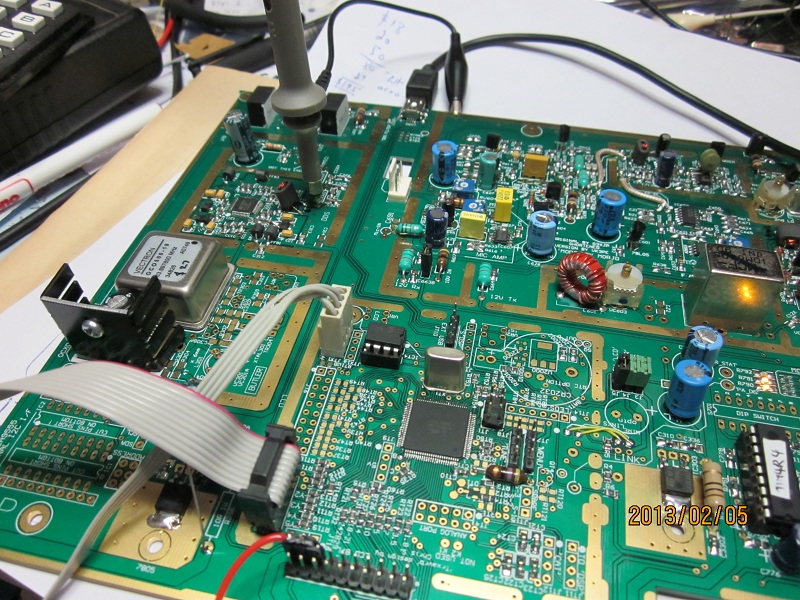
 VK3PE's P1 build progress. Trxavr is controlling the DDS, driven from an experimental
OCXO reference. The regulator gets quite warm, it may need additional heatsinking
or perhaps a dropper resistor on the input supply to the LM317. (LATER:- an
additional smaller heatsink was bolted on the rear of the larger one)
VK3PE's P1 build progress. Trxavr is controlling the DDS, driven from an experimental
OCXO reference. The regulator gets quite warm, it may need additional heatsinking
or perhaps a dropper resistor on the input supply to the LM317. (LATER:- an
additional smaller heatsink was bolted on the rear of the larger one)
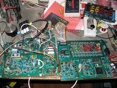
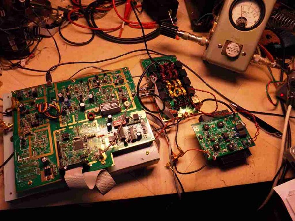
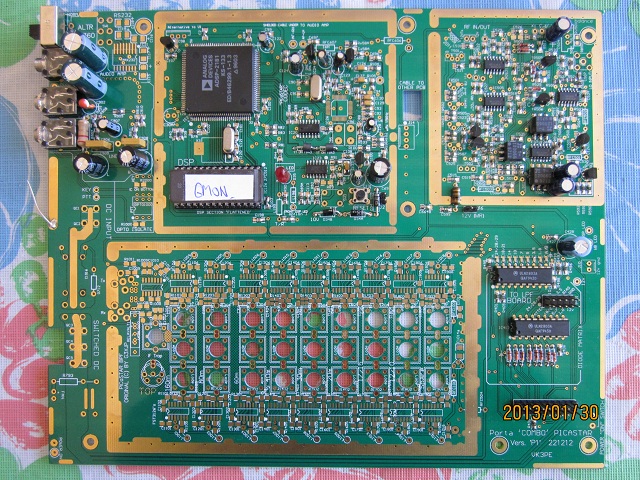 The other PCB section is almost complete. The DSP LED flashes too! I normally
load and wind the BPF coils etc last in my builds. Unlike previous COMBO boards,
the RS232 port is now a stereo jack, to save space.
The other PCB section is almost complete. The DSP LED flashes too! I normally
load and wind the BPF coils etc last in my builds. Unlike previous COMBO boards,
the RS232 port is now a stereo jack, to save space.
22nd
Feb 2013, the Combo P1 is now receiving signals. After some issues with
a dodgy ATMEGA chip (bought out of China on ebay) very pleased to report the
VK3PE build has received it's first signals on 40M today. Sensitivity is on
a par with previous builds. (~-127dBm) The BPF is not yet fitted. Some more
work to do on the case to tidy things up from the "bench" tests to
go. Excuse the messy work bench too ! Click
here to see and hear a QSO on 40M. (4MB AVI file)
 click picture for larger size.
NEW:- Feb 13th,
2014 You might notice I hand wound the
two inductors (L3301, L3302) in the DDS filter area. The values are from 'Bob's
mods' and are not off the shelf part values. Some builders use toroids, I elected
to use air wound. They were calculated from an on-line calculator and confirmed
with an AADE LC meter. For a closeup look at them,
a picture is here. It includes the winding information.
NEW, 3rd March, 2013:
There are more pictures here of the
build so far which will also give you an idea of the interconnections also.
 See link above for more details of the VK3PE
build and homebrew case.
See link above for more details of the VK3PE
build and homebrew case.
PCB's:-
Occasionally, a group buy for Homebrew-radio
Yahoo group members is undertaken.
November,
2017, there are NO current plans to order PCB's.
Cost has risen I am afraid,
mainly due to the plunge in AUS Vs US$ exchange rates. When I started making
'P1' version, the rate was $1.05. It's now around 68c and still falling. (bank
rate) This impacts severely on the final cost. This means the PCB set cost
is close to AUS$100. Sorry, nothing I can do about this.
This includes postage,
packing materials and Paypal levy. NB. TFTA
pcb is not included. (refer to VK3CG)
Please note... there is no insurance
or tracking offered on the postal service. Future orders (if any)
may vary in cost (up or down) as there are many factors involved in the group
buy.
Enquire.
EMAIL VK3PE, see QRZ.COM
WHAT PCB's DO YOU GET?
The "P1"and "P2/a" version PCB
set includes all of the PCB's you
need only, (it
is not a kit, no parts are supplied) , to build a working
PICASTAR:-
The main "P2a" PICASTAR boards, combined
into two parts as above, plus;
20W PA, 140W PA and LPF boards. (The
P2/a panel now also includes the end pcb's for the 140W PA output transformer.)
A remote USB interface PCB. This
PCB allows the USB port to be extended to the rear or front panels, as you
wish.
A small PCB to make the original G3XJP optical
tuning encoder. Some builders use commercial encoders though. NB: the original
type specified is 180 pulses.
A low probe voltage "Beeper"
board for testing. Beeper
board schematic. The BOM
kindly supplied by Bill, N4BKT, 31st Dec 2009. Beeper
board wiring diagram
Use this Beeper board to check connections
etc with low voltage probes, which won't damage any parts. It is suggested
you make this PCB FIRST as it will give you a little practice with SMD parts
and wiring etc.
What is not included
is the colour display interface board, called "TFT_A". This
TFT_A board is only available from VK3CG.
UPDATE, 29th
Nov, 2013, It's believed that
VK3CG may have now run out of full kits, but plenty of the TFTA PCB's are
available. Check directly with VK3CG. There is a Yahoo TFT
group also, where you can contact VK3CG.
The correct type of 4.3 or 5" TFT display needs
to be bought off eBay. Details are on the TFT
users group.
Please note,
this project can be fitted with up to 8 optional Encoders which can be programmed
for various tasks. Provision for this is part of the TFT_A board. If you do
not fit the TFT display, then the encoders will require an additional interface
board (Encoders8) which is NOT included.
Trxavr
'Controller'
& CHOICE of DISPLAY
PICASTAR originally
used 6 x 7 segment LED displays. Later, Ian, G3VPX, developed a new controller,
called TrxAVR. ( This controller is integrated
onto Combo P1 & P2/a and allows the use of more modern displays using LCD's
and later, also catered for a full colour TFT display.)
The Trxavr section of the Combo P1/P2
board is included in the BOM for the main PCB. You need to refer to G3VPX's
web pages for full info on programming (including the software) of the
Trxavrb section. Also, the TFT display.
See here:- G3VPX's
TrxAVR Interface web pages.
NOTE:-
There is currently no PCB for an 'Encoders 8' PCB. Schematic
This would be required if you wish to fit encoders
without a TFT display. The set of PCB's supplied assumes most will use
a TFT display.
To use the TFT display,
a separate PCB, (not provided with COMBO) is required. TFTA
PCB's are available from VK3CG. VK3PE does not have permission to sell
this PCB. It is NOT included in the boards supplied by VK3PE.
Suggested
display wiring diagrams.
Please ensure you have
data for the display you wish to use, as pin-outs can vary. This diagram
shows the wiring from the Combo PCB, in the Trxavr controller area.
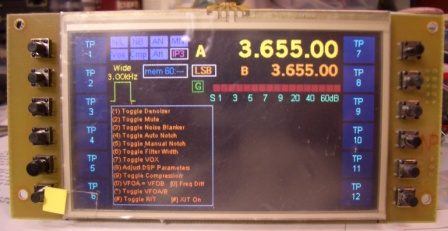
TFT DISPLAY
The TFT display interface
PCB was designed by Chris Stake with software by VK3CG. It can only be used
with the Trxavr controller which is on Combo boards but is not a part of the
priginal G3XJP design. It can be retro fitted though.
The actual TFT display
can be bought in either 4.3" or 5" sizes on eBay and other on-line
stores, very cheaply. (typ. $25) Touch screen types are also catered for in
the design. An estimate for the TFT display option is about AUS$90 - 100 which
would include the PCB and parts plus the TFT display itself. See the information
in the files section of the Yahoo "TFTA_Central"
group for correct TFT models.
There is some
information here on setting up, and programming the TFT PCB if you are fitting
a TFT display.
Remember, a "TFT_A"
interface PCB is required to use a TFT display.
NOTE:
some TFT displays are better mounted with the ribbon cable at the bottom, as
the viewing angle is better. Check yours before final fitting into case. The
TFT_A PCB has provision (with a link) to 'invert' the display in software.
Other LCD displays
can also be used, both character
based and graphical. (Not touch screen though) Refer to the "Combo C"
version pages for information on connecting these types.
Band
Pass Filter section.
The BPF is closely based on the original
design by G3XJP, but the inductors are now on the top and Lodestone formers
can now be fitted. The recommended Toko™ and some other '10mm' types can
be fitted also.
http://www.Digikey.com
in the USA have the FST3125
and FST3126
devices, for example, at reasonable costs but shipping should be factored in
also. A group buy would be better, as costs drop rapidly with increased numbers
bought.
There is some information here
and here
(coil winding) which may be useful for coil winding, if using Toko 10K™
formers.
Toko pre-wound coils
are more difficult to buy these days, but
some data here may be helpful. Some
builders have fitted small Toroids with good results, but it's quite tedious
to tune them. No information is currently available on toroid type and winding
details.
PA3AKE has done a lot of work in developing a very high performance BPF. Some
builders have fitted this in place of the PICASTAR BPF but be aware that the
PA3AKE BPF
is very large. There are some
pictures here of one PA3AKE build. Some have built a smaller
version of the PA3AKE BPF with homebrew PCB's by using smaller toroids.
Performance will be lower than the original PA3AKE version, but probably more
than adequate. The Trxavrb controller and Hobcat allows this BPF to be fitted
using an I2C interface which is included on version P1 boards. (PCA9555)
Dan,
AC6AO, has built a toroidal
version BPF using the existing STAR PCB's.
Expanding on this idea
of using Toroids in the BPF, VK3PE has made available some small PCB's that
can be fitted with a Toroid version of the BPF filters and be fitted over the
appropriate band position on the Combo boards BPF section. NOTE:
this is essentially experimental as VK3PE has not fitted a full set of these
PCB's to his own STAR builds, but it is very similar to the toroid version by
Dan, in the link above. In fact, the winding information is based on Dan's good
work.
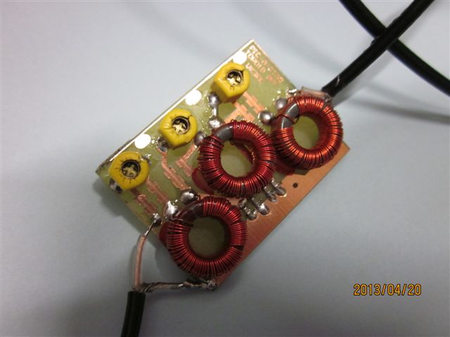
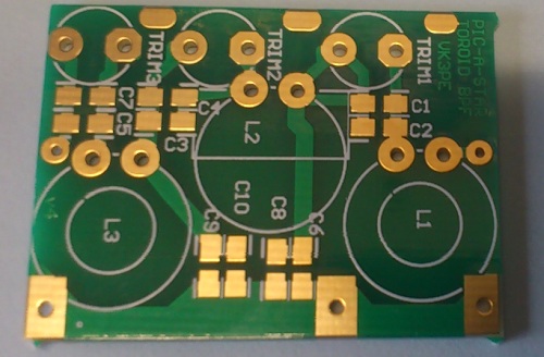 10 of these were included on a "Toroid BPF" panel which may still
available from VK3PE.
10 of these were included on a "Toroid BPF" panel which may still
available from VK3PE.
More Toroid information on this
new page. Toroid
adapter PCB's for BPF
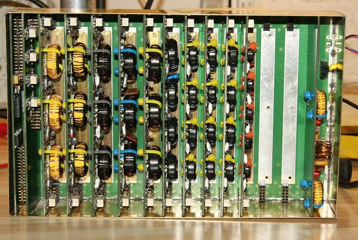 The PA3AKE front end, as built by G3VPX.
If you decide to use the PA3AKE front
end BPF, Trxavrb controller has provision
for setting bands with the PA3AKE BPF in the Hobcat
setup program. The BPF on the Combo boards is easily bypassed and of course,
you will not load those components.
TOKO™
Coils
G3XJP's original design
used Toko coils. While no longer made, they can still be found on eBay, in old
CB radios and new from some suppliers in the UK, although not all of the part
numbers specified by G3XJP are available. Mostly, you will need to rewind any
Toko coils found. Refer to the information and links above. The P1 and P2 pcb's
can take Toko coils and also Lodestone types.
'Slot-10' can also be fitted
but their Q is not so good.
There
were some Toko style coils on ebay at one time with only a single winding area.
I don't know if they are usable on all bands, if at all, but one builder
has played with some and I
include his 20M band info here. And also 160M
here. Leonid has given me some
preliminary winding details for each band but please note, these are UNTESTED
and are not guaranteed to give exact equivalent BPF's to that using the specified
Toko 10k coils. For example, the IP3 or bandwidth might well be poorer.
LODESTONE™
and also Slot-10 Coils
The PCB will take these
Lodestone coils also and in fact, they are reputed to be a better part. They
cost about $2.50 each and occasionally a group buy will take place on the Yahoo
groups for those interested and the price will fall a little. VK3PE has no direct
knowledge of where they they can be purchased though but would assume somewhere
in USA.
Suggested
Combo PCB build method.
Wondering
where/how to start? Check
here. This is for the "B" version, but "P1" & "P2/a"
versions will be very similar.
The above
link pages are not an official PICASTAR build method. You should also have read
all of the original articles by G3XJP, located on the Yahoo "picaproject"
group. You need to be a member of this group to obtain the documents and software.
INTEGRATION
(HOW THINGS CONNECT TOGETHER)
UPDATED! March
11th, 2013. The integration
drawing (3.2MB) now updated, mostly just tidied up.
Feb 8th, 2013, (this is the older drawing, for
reference only) An integration
drawing (draft) (2MB pdf) is now available, to assist with the inter-wiring.
If you see anything that is not clear, let me know.
23rd Feb, 2013:
There are more pictures here of the
build so far which will give you an idea of the interconnections also.
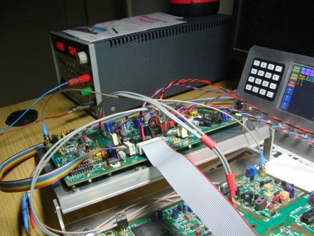
CABLES:
There are pictures here which
will give you an idea of the interconnections
The two main PCB's connect together using a 20 way
IDC cable. Plus, a 10 way IDC cable connects to the LPF board. NOTE: only one
end of this 10 way cable uses an IDC connector as the LPF has a single row of
pins..
A 4 way cable connects the DSP 15KHz signals and
the cable is passed through a small cutout in each PCB which has been arranged
to be over the top of the lower PCB to allow the cable to be passed though a
hole in the chassis, if desired. It is optional to use the cut-outs.
Several small co-ax cables (eg RG-174 etc) are fitted
under the PCB's for RF interconnects. Also, small co-ax (eg RG178) is used to
connect the main PCB (BPF area) to the LPF and 20W PA input. Provision for fitting
SMA connectors is on the PCB but this is not mandatory. You can simply solder
the cables to the PCB's. RG178 is often found on eBay.
A twin core shielded audio cable is also required
between the Trxavr section and the DSP RS232 switch area.
DC power input [13.8V] is connected to the PCB using
'quick connect' tabs or QC tabs. The DC supply passes through a reverse polarity
protection relay to more QC tabs, for connection to the PA's. Don't skimp on
the cables used as high currents are involved here, especially if running the
140W PA. Use two parallel cables for the 140W PA. Also, make sure the PA's are
well grounded. I usually use some co-ax cable braid from the PA back the DC
input area.
RS232 Cable.
You will need to make a test cable for using G3XJP's various programs and laoding
DSP etc. The cable detail is DIFFERENT to that used by G3XJP and is detailed
in the schematics. Refer to link above for Schematics download.
Making
the shields,
a suggested method. Shown
for earlier Combo versions, but principle is same for P1, P2 etc version.
All versions
of the Combo board require shielding around the various circuit 'blocks'. However,
you can build the whole radio without them initially and test it first.
And updated
with info from Dan Rae
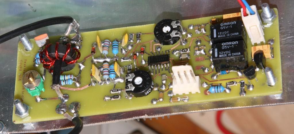
High
SWR protection. There is an input on the TIMER
section (PIC16F627) for disabling the transmitter ("TX_DISABLE"),
if high VSWR is present. This requires an additional board that integrates into
the Trxavrb controller firmware and is NOT supplied
with the VK3PE board set. With this PCB, forward and reverse power is indicated
on the TFT screen when in Tx mode.
Further information on this option
is here on G3VPX's web pages.
NOTE, the TIMER PIC code needs to be the one that
has been modified by G3VPX for this purpose. (It disables the PA if there
is high SWR) This might be found on G3VPX's web pages, I think. Or possibly
is part of the Hobcat
download files and already on your PC. You will need to download Hobcat
anyway.
A 'commercial' PCB is not normally
available for the "peakswr" protection. A copy of the pcb copper for
home brew is on Ian's web pages.
April
2014: VK3PE had a small number of these made,
with some small changes to Ian's original. eg. The relays are no longer used
for peak switching. FET's are used instead. In my initial build, I used an LM324
op-amp. This is not the reccomended part! The original design uses a rail to
rail type op-amp. Using an LM324, the output positive excursion will be limited.
NB This PCB is a little shorter and
slightly wider (100mm x 43mm) than the original (right hand picture). Overlay.
BOM.
BOM
(Xcel) Schematic.
Only a
few ( 8, . one left) of these PCB's available:-
AUS$8.90 incl. postage anywhere. NONE left.

Need Ideas to build
your PICaSTAR ??
There are more ideas on
building in the Builders pages.
Also, see the link on Combo
"B" version builders
pages.
Latest entries:
Cristi,
YO3FLR.
Enno,
DK5NOA.
Sanyi
HA2NJ has updated his modular STAR with Trxavrb and TFT
Nick,
UY5QQ's modular STAR build is now receiving signals. 5th
May 2014
Carlos,
EA1CGK's magnificent build NEW July 2017
Some ideas
on tools etc. This is for the modular STAR but might be of some use.
Need
a CASE and would like to make one? Some ideas here using aluminium extrusions.
 Here
are two fine examples using PCB
material for the case. [Left Star uses a 128x64 display, right uses a colour
TFT display] Roger had a supplier pre-cut the 2mm thick PCB material for him,
to save some work.
Here
are two fine examples using PCB
material for the case. [Left Star uses a 128x64 display, right uses a colour
TFT display] Roger had a supplier pre-cut the 2mm thick PCB material for him,
to save some work.
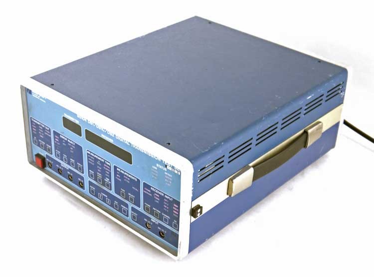
Here (below, left) is a typical 'old'
instrument available on eBay that can be stripped and used to make a nice case
for your STAR. This one is probably not available still but was titled "General
Signal Tau-Tron S5104 DS1-DS1C-DS2 Digital Transmission Test Set PARTS "
and was only $28 plus postage. Within USA postage was reasonable but watch out
if you are not in the USA as this vendor charges over the top for shipping !
However, it will give you a good idea on what to look for and you can see just
how nice these cases can be, as the picture by Dan (AC6AO) shows, using this
same case. Always ask the vendor for the dimensions BEFORE buying though.
 Dan, AC6AO's build (click for bigger picture)
Mats SM0RJV Jan 4th 2015:-
(below) Home built PCB's now on air. Magnificent work. Mats has also built a
TFT based Panadapter.
BUILDERS
PAGES, Combo P1, P2, P2a versions.
A few of the builders have now made
excellent progress on their new Combo "P1, P2/a" builds. Here are
some, that sent in photo's. Click on the pictures for even more information.
Michel,
F1CHM
 Now on air !! 27th Mar, 2013
Dan,
AC6AO
 Dan is well advanced
Leonid,
4Z7LES
Glenn,
VK3PE (author of this page)
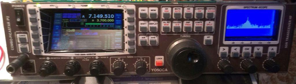
Aurel,
YO5OCA
Aurels 2nd build with 64KHz wide
Panadapter also (Elm-ChaN design) Sept 2015
Roger
HB9LFU
 Roger,
HB9LFU
Roger,
HB9LFU
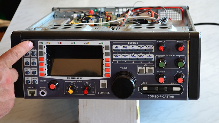
Tony,
G4LFU
 Picture clearly shows the intended 'stacking' of
the P series PCB's.
Picture clearly shows the intended 'stacking' of
the P series PCB's.
More from Tony, his P1 build now
in a case.
Click to see more details
 Ken, G3LVP, P2 now on air.
Dave, M5TXJ has almost finished assembling his P2a PCB
(click
for pictures)
John, G0IJK's "P2a" build progress. Oct 2014. Click
picture for more. NEW Updated Jan 2016
April 2015
Michel, F1CHM, sent me these
pictures of an incredible 9th Picastar build.
NEW June 2016:-........
Earle, AB6WL, has made his own versions of Star boards. eg upper left DSP &
Codec, upper centre, AF amp RS232 & opto. Bottom, Trxavr-Matrix-Timer.
NEW June 2016:-.
Yuriy, UW5EHL, almost has his Combo Star finished.
(picture below)
Carlos,
EA1CGK's magnificent build NEW July 2017
Some
IDEAS ON HOUSING YOUR STAR -->> NEW 26th
Jan 2013
This a drawing of how a
front panel could look, trying to keep the size to a minimum, consistent with
the smaller PCB size of the P1 Combo boards. You can make a layout as you wish
of course, larger and maybe even smaller if you are able to. One way would be
to use an LCD display and no encoders except for MENU. The Mic. Socket could
also be relocated to the side of the case. (The width of the PCB also needs
to be accommodated. In this drawing, the case is wider than the actual PCB behind)
A layout like this would probably also need a custom made case in aluminium
or made with PCB material unless you were very lucky finding a suitable case
to use. The size of this panel is 220 x 110mm in size. Those dealing in inches
might have to convert this! [divide by 25.4] Click the picture for a
pdf version, also. It should be printed with no scaling, for an A4 paper
sheet.
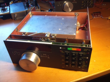
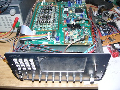
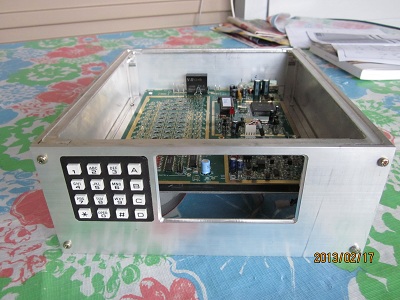
Feb
17th 2013: VK3PE
is currently building a home brew case based on drawings below. Although now
240mm wide, to accommodate the 4x4 keypad instead. Only one encoder (Menu) is
planned for the build, although may add more later.
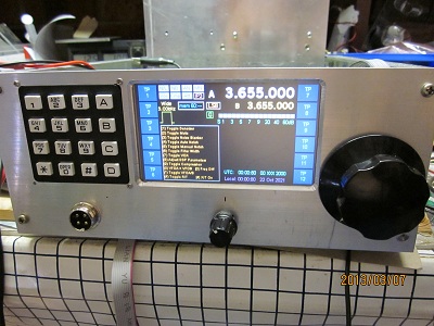
Below is
the progress so far. Based on the ideas below but 240mm wide as described above.
Some changes to the drawings (originals still shown here) were made to suit
the construction better. Case is made from 100mm "U" shaped aluminium
extrusion. This type has a 25mm flange and is 3mm thick. For those dealing in
inches, about 4" x 1" x 1/8" thick. In my build, I elected to
cut the top flange down in width, for better internal access.
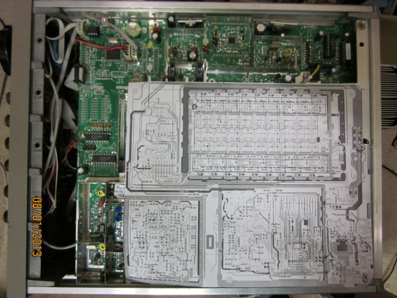
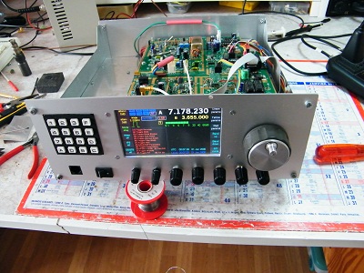
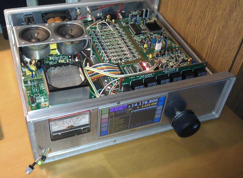
A sub chassis
plate is mounted on some further angle extrusion mounted down low. The PCB with
the BPF section it, is visible. The other board will be underneath. An upper
sub chassis will be added later for the 20W PA & LPF. The 140W PA, if used,
will go on the back with suitable heatsink.
Click for
larger picture.
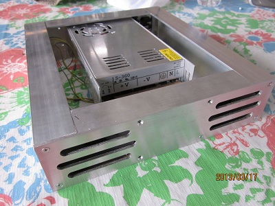
March 2013,
Above is a home brew matching power supply and speaker enclosure, made using
60mm high "U" shaped extrusion to the same dimensions as the Transceiver,
in a similar fashion. Not quite finished as yet.
 This
is similar to one built by VK3PE, above.
This
is similar to one built by VK3PE, above.
The above drawing is for information
only and provided as a guide. Any layout is possible, you may prefer the tuning
encoder on the other side for example.
**
No panels or parts are supplied by VK3PE. **
A minimal PICASTAR using Trxavrb
controller, only requires a display (TFT or LCD), the keypad, tuning encoder
and MENU encoder.
The pictures above are not
necessarily a "how to build this radio", just to get you thinking
on making your own PICASTAR. They do not include internal speakers or power
supplies. Everybody will have their own ideas on construction. I would be happy
to include any builders ideas and pictures of their build, on these pages.
TUNING ENCODER
Making
a tuning encoder. A PCB is supplied for this as per the original G3XJP design,
and the parts to build it are included in the BOM.
Some builders
use encoders off eBay. The recommended pulses per turn is 180 but these are
not easily available, so many use 120 or even 256 pulse commercial opto encoders,
which will obviously affect the tuning rate, when used in STAR. A common encoder
found on eBay is the Oak-Grigsby 120 pulse type at reasonable cost (about $30
or so). They tend to be a little stiff to turn but work OK. ie they do not 'spin'.
Avago make very nice encoders but these tend to be in the order of $100 and
more.
Yahoo groups
which are very helpful in this project.
You MUST be a member of the Yahoo™ 'picaproject'
Group for access to the latest files and software. You need to join this group
and digest all the information contained there on the project and especially
the set-up information.
It is also very helpful to be a member of the
'homebrew-radios'
and 'picastar users'
groups. Refer to those groups for information on joining. For the later, you
must be a member of the above picaproject group also.
If you wish to fit the colour display option,
there is a 'TFTA_central'
Yahoo group also.
For future group buys of
PCB's refer to email below please.
NOTE ! These
PCB's were prepared in good faith, as a labour of love. Although carefully checked
and preceded by the previous Combo versions, errors can occur in design and
also in the PCB making process. <vk3pe>
vk3peATbigpond.com
This page
will be updated further when more information is available.
Page created on 18th Dec, 2012 by
vk3pe & last updated on November 20, 2017


